
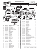
Service Parts List S/N C07A

2
1
1
2
3
4
5
6
7
RED
BLACK
BLACK
RED
WHITE
RED
BLACK
TERMINAL BLOCK
ASSEMBLY
MOTOR
ASSEMBLY
SWITCH
ASSEMBLY
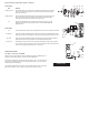
1 Red 14 ----- Component of the Switch Assembly 23-66-2960.
2 Black 14 ----- Component of the Switch Assembly 23-66-2960.
3 Red 14 ----- Component of the Switch Assembly 23-66-2960.
4 Black 14 ----- Component of the Switch Assembly 23-66-2960.
5 White 28 ----- Component of the Switch Assembly 23-66-2960.
6 Red 28 ----- Component of the Switch Assembly 23-66-2960.
7 Black 28 ----- Component of the Switch Assembly 23-66-2960.
Terminals, Connectors and 1 or 2 End Wire Preparation
Wire
Color
Origin or
Gauge
Wire
No.
Length
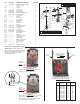
WIRING SPECIFICATIONS
AS AN AID TO REASSEMBLY, TAKE
NOTICE OF WIRE ROUTING AND
POSITION IN WIRE GUIDES AND
TRAPS WHILE DISMANTLING TOOL.
BE CAREFUL AND AVOID PINCHING
WIRES BETWEEN HANDLE HALVES
WHEN ASSEMBLING.
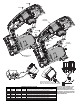
3
4
5
6
7
7
6
5
Insert connector into the
bottom of the switch as shown.
Note, the connector must be fully seated.