
Use and Care Manual


5
SPECIFICATIONS
Cat. No. ..................................................... 2680-20
Volts .............................................................. 18 DC
Battery Type .................................................M18™
Charger Type ................................................M18™
Rated RPM ...................................................10,000
Spindle Thread Size .................................... 5/8"-11
Max Capacity .......................................4-1/2" x 1/4"
SYMBOLOGY
Volts
Direct Current
Rated Revolutions per Minute (RPM)
C
US
UL Listing Mark for Canada and the U.S.
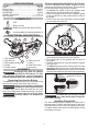
FUNCTIONAL DESCRIPTION
1. Side handle
2. Spindle lock
3. Side handle sockets
4. Handle
5. Paddle switch
1
5
6
7
8
3
2
6. Switch lock-o
7. Guard
8. Guard lock lever
9. Accessory
4
9
ASSEMBLY
WARNING
Recharge only with the charger
specied for the battery. For spe-
cic charging instructions, read the operator’s
manual supplied with your charger and battery.
Removing/Inserting the Battery
To remove the battery, push in the release buttons
and pull the battery pack away from the tool.
WARNING
Always remove battery pack before
changing or removing accessories.
To insert the battery, slide the pack into the body
of the tool. Make sure it latches securely into place.
WARNING
To reduce the risk of injury when
grinding, always use properly in-
stalled guards.
Removing/Installing/Adjusting the Guard
This tool is shipped with a guard. A guard must be
used when using the tool as a grinder. The guard may
be removed when using tool as a sander.
1. To remove the guard, remove the battery pack
and remove any accessories from spindle.
2. Press in the guard lock lever and rotate the guard
to line up the tabs on the grinder with the slots in
the guard.
3. Press in the lock lever and lift the guard straight
up and away from the tool.
Tab
slots
Detent
slots
4. To install the guard, remove the battery pack and
remove any accessories from the spindle.
5. Line up the tabs on the grinder with the slots in
the guard.
6. Press in the guard lock lever and press the guard
onto the tool.
7. To adjust the guard, press in the guard lock lever
and rotate the guard to one of ve detent slots.
WARNING! Always adjust the guard to provide the
operator with maximum protection while operating.
Operator's Zones
WARNING
To reduce the risk of injury, always
use a side handle when using this
tool. Hold securely.
Installing Side Handle
The side handle may be installed on either side of
the gear case. Position the side handle in the loca-
tion which oers best control and guard protection.
To install, thread side handle into side handle socket
and tighten securely.