
Use and Care Manual


4
5
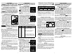
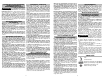
Allow the tool to come to a complete stop before
changing modes. Press the selector button to
cycle between the settings. Select wireless to
change the default RPM settings via the ONE-KEY
App on your smart device.
Default Max RPM
High
Low
Setting 1 Setting 2 Setting 3 Setting 4
1 200
300
1 450
375
1 700
425
2 000
500
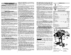
Selecting Speed
The speed selector is on top of the motor housing.
Allow the tool to come to a complete stop before
changing speeds. See “Applications” for recom-
mended speeds under various conditions.
1. For Low speed, push the speed selector to display
“1”.
2. For High speed, push the speed selector to display
“2”.
Using the Control Switch
The control switch may be set to three positions:
forward, reverse and lock. Due to a lockout mecha-
nism, the control switch can only be adjusted when
the ON/OFF switch is not pressed. Always allow the
motor to come to a complete stop before using the
control switch.
Lock
Push to
CENTER
Reverse
Forward
For forward (clockwise)
rotation, push in the con-
trol switch from the right
side of the tool. Check
the direction of rotation
before use.
For reverse (counterclockwise) rotation, push in the
control switch from the left side of the tool. Check
direction of rotation before use.
To lock the trigger, push the control switch to the
center position. The trigger will not work while the
control switch is in the center locked position. Always
lock the trigger or remove the battery pack before
performing maintenance, changing accessories,
storing the tool and any time the tool is not in use.
WARNING
To reduce the risk of injury, always
always hold or brace securely.
Starting, Stopping and Controlling Speed
1. To start the tool, grasp the handles fi rmly and pull
the trigger.
NOTE: An LED is turned on when the trigger is
pulled.
2. To vary the speed, increase or decrease the pres-
sure on the trigger. The further the trigger is pulled,
the greater the speed.
3. To stop the tool, release the trigger. Make sure
the bit comes to a complete stop before laying the
tool down.
Drilling
Place the bit on the work surface and apply fi rm pres-
sure before starting. Too much pressure will slow the
bit and reduce drilling effi ciency. Too little pressure
will cause the bit to slide over the work area and dull
the point of the bit.
If the tool begins to stall, reduce pressure slightly to
allow the bit to regain speed. If the bit binds, reverse
the motor to free the bit from the workpiece.
ASSEMBLY
WARNING
Recharge only with the charger
specifi ed for the battery. For spe-
cifi c charging instructions, read the operator’s
manual supplied with your charger and battery.
Inserting/Removing the Battery
To remove the battery, push in the release buttons
and pull the battery pack away from the tool.
To insert the battery, slide the pack into the body
of the tool. Make sure it latches securely into place.
WARNING
To reduce the risk of injury, always
use a side handle when using this
tool. Always brace or hold securely. Ensure side
handle is tightened securely before each use.
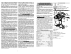
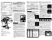
Installing the Side Handle
1. To install the side handle,
Hooks
Slots
loosen the side handle grip
until the hooks are far
enough apart to fi t into the
slots on the gear case ring.
Position the side handle on
the top, pointing to the left or
right. Tighten the side han-
dle grip until it is secure.
2. To remove the side handle,
loosen the side handle grip
until the side handle can be
removed. Reposition and
tighten securely.
WARNING
Always remove battery pack before
changing or removing accesso-
ries. Only use accessories specifi cally recom-
mended for this tool. Others may be hazardous.
Installing Bits
Always remove the battery before inserting or remov-
ing bits. Select the proper style and size bit for the job.
This tool is equipped with a spindle lock. The chuck
can be tightened with one hand, creating higher grip
strengths on the bit.
1. To open the chuck jaws, turn the sleeve in the
counterclockwise direction.
When using drill bits, allow the bit to strike the
bottom of the chuck. Center the bit in the chuck
jaws and lift it about 1/16” off of the bottom.
When using screwdriver bits, insert the bit far
enough for the chuck jaws to grip the hex of the
bit.
2. To close the chuck jaws, turn the sleeve in the
clockwise direction. The bit is secure when the
chuck makes a ratcheting sound and the sleeve
can not be rotated any further.
3. To remove the bit, turn the sleeve in the counter-
clockwise direction.
NOTE: A ratcheting sound may be heard when the
chuck is opened or closed. This noise is part of the
locking feature, and does not indicate a problem with
the chuck’s operation.
ONE-KEY™
To learn more about the ONE-KEY functionality for
this tool, please reference the Quick Start guide in-
cluded with this product or go to milwaukeetool.com/
One-Key. To download the ONE-KEY app, visit the
App Store or Google Play from your smart device.
APPLICATIONS
WARNING
To reduce the risk of electric shock,
check work area for hidden pipes
and wires before drilling or driving screws.
Drilling in Wood, Composition
Materials and Plastic
When drilling in wood, composition materials and
plastic, select the
drill-only operating mode.
Start the drill slowly, gradually increasing speed as
you drill. When drilling into wood, use wood augers
or twist drill bits. Always use sharp bits. When using
twist drill bits, pull the bit out of the hole frequently to
clear chips from the bit fl utes. To reduce the chance of
splintering, back work with a piece of scrap wood. Se-
lect low speeds for plastics with a low melting point.
Drilling in Metal
When drilling in metal, select the drill-only oper-
ating mode. Use high speed steel twist drills or hole
saws. Use a center punch to start the hole. Lubricate
drill bits with cutting oil when drilling in iron or steel.
Use a coolant when drilling in nonferrous metals such
as copper, brass or aluminum. Back the material
to prevent binding and distortion on breakthrough.
Drilling in Masonry
When drilling in masonry, select the hammer
drill operating mode. Use high speed carbide-
tipped bits. Drilling soft masonry materials such
as cinder block requires little pressure. Hard
materials like concrete require more pressure.
A smooth, even fl ow of dust indicates the proper
drilling rate. Do not let the bit spin in the hole
without cutting. Do not use water to settle dust or
to cool bit. Both actions will damage the carbide.
Driving Screws and Nut Running
Drill a pilot hole when driving screws into thick or hard
materials. Select the driving screws mode. Set
the torque selector collar to the proper position and
set the speed to low. Use the proper style and size
screwdriver bit for the type of screw you are using.
With the screwdriver bit in the screw, place the tip of
the screw on the workpiece and apply fi rm pressure
before pulling the trigger. Screws can be removed
by reversing the motor.
Overloading
Continuous overloading may cause permanent dam-
age to tool or battery pack.
OPERATION
WARNING
To reduce the risk of injury, wear
safety goggles or glasses with side
shields.
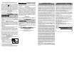
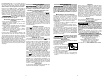
Selecting Action
1. To use the hammer-drilling
mode (Cat. No. 2706-20 only),
rotate the application selector
collar until the hammer symbol
appears in line with the arrow.
Apply pressure to the bit to en-
gage the hammering mechanism.
NOTE: The number selected on the torque selec-
tor collar has no effect on operation of the drill in
this mode.
NOTE: When using carbide bits, do not use water
to settle dust. Do not attempt to drill through steel
reinforcing rods. This will damage the carbide bits.
2. To use the driving screws mode
rotate the application selector
collar until the drive symbol
appears in line with the arrow.
Then rotate the torque selector
collar until the desired clutch set-
ting appears in line with the arrow.
The adjustable clutch, when properly adjusted, will
slip at a preset torque to prevent driving the screw
too deep into different materials and to prevent
damage to the screw or tool.
The torque specifi cations shown here are approximate
values obtained with a fully charged battery pack.
Clutch
Setting in. lbs Applications
1
2
3
4
5
6
7
8
9
10
11
12
13
30
35
40
45
50
55
60
65
70
75
80
85
90
Small screws in softwood.
Medium screws in softwood or
small screws in hardwood.
Large screws in softwoods. Me-
dium screws in hardwood or large
screws in hardwood with pilot hole.
NOTE: Because the settings shown in the table are
only a guide, use a piece of scrap material to test
the different clutch settings before driving screws
into the workpiece.
3. To use the drilling only mode,
rotate the application selector
collar until the drill symbol
appears in line with the arrow.
NOTE: The number selected on
the torque selector collar has no
effect on operation of the drill in
this mode.
4. To use the Mode Selector
buttons, rotate the application
selector collar until the wireless
symbol
appears in line with
the arrow.
NOTE: The number selected
on the torque selector collar has
no effect on operation of the drill in this mode.
Hammer-drilling is not available in this mode.