
Replacement Part List

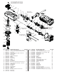


AS AN AID TO REASSEMBLY, TAKE NOTICE OF WIRE ROUTING AND POSITION
IN WIRE GUIDES AND TRAPS WHILE DISMANTLING TOOL.
BE SURE THAT ALL COMPONENTS OF THE ELECTRONICS KIT ARE SEATED
FIRMLY AND SQUARELY IN THE HANDLE RECESSES.
AVOID PINCHED WIRES, BE SURE THAT ALL WIRES AND SLEEVES ARE
PRESSED COMPLETELY DOWN IN WIRE GUIDES AND TRAPS.
PRIOR TO INSTALLING THE HANDLE COVER ONTO THE HANDLE SUPPORT,
BE SURE THAT THERE ARE NO INTERFERENCES.
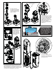
Place approximately 8.11 ounces
(230 grams) of ‘Y’ Grease down
and around the gear and clutch
mechanism inside the gear case.
Place approximately 1.76 ounces
(50 grams) of ‘Y’ Grease around
the bevel pinion and bevel gear
cavity of the gear case.
Place approximately 2.11 ounces
(60 grams) of ‘Y’ Grease into
this area of the diaphragm
assembly.
LUBRICATION NOTES:
Type ‘Y’ Grease No. 49-08-5270, 6oz./170g tube
The entire amount of two tubes will be needed.
or
Type ‘Y’ Grease No. 49-08-5275, 14oz./396g tub (can)
When servicing, remove 90-95% of the existing grease prior to installing Type 'Y'.
Original grease may be similar in color but not compatible with 'Y'.
DO NOT wash Clutch Hub Assembly #95. Prior to reinstalling, clean gear assemblies with a clean, dry cloth.
NOTE:
Disconnect/unscrew the High Voltage Wire
from the Diaphragm and remove wire from
traps prior to removing Electronics Assembly.
Battery
Connector
Block
On-Off Switch
Inside Motor Cage Assembly:
Rotor, Stator and PCBA
High Voltage Wire
(Ground Terminal)
LED
Assembly
Ribbon Cable
= WIRE TRAPS
or GUIDES
WIRING DIAGRAM