
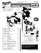
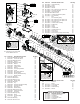
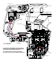
Service Parts List


28a
28b
28
18a 18b
18c
18
7
1
2
3
4
5
6
15
14e
14d
14c
14b
14a
25
24
20
19b
19a
16
17a
17b
18a
18b
18c
17c
17d
17c
17e
17f
17g
17h
31d
31c
31a
31b
28b
28a
27
22b
36a
29a (4x)
30
26
17a 17b 17c 17d 17e
17f 17g 17h 18
17
19a
19b
19
33
34
35
19b
36b
36c
37
38
39
19b 36a
36b 36c
36
29b (2x)
31a 31b
31c 31d
31
29b
(2x)
29a
(4x)
DO NOT exceed
40 In/Lbs for #29b
There are slightly
smaller teeth
on one side of
drive sleeve
#34 that are to
face the spindle
bevel gear #33.
17h 20
Washer
#20 is to be
located here on
barrel #17h
17c
Position
tapered side
of rebound rings
#17c to face striker #19
and anvil #18 as shown
14a 14b 14c
14d 14e
14
9
8
12
11
10
13
14a
24
14a (Back side)
Be sure to orient front notches of bearing shield
#14a at the 12:00/6:00 position or at the 9:00/3:00
position prior to installing in gearcase #24. Doing
so will allow tabs in rear of bearing shield to
seat in corresponding notches in gear
case cavity. This must be done to
allow for proper seating of
retaining ring #13.
FIG. PART NO. DESCRIPTION OF PART NO. REQ.
19 45-56-5316 Striker Assembly (1)
19a 45-56-5320 Striker (1)
19b 34-40-5310 O-Ring (2)
20 45-88-5314 Washer (1)
22b 05-78-5316 M4 x 14mm Pan Hd. Taptite T-20 (2)
24 14-29-0028 Gearcase Assembly (1)
25 14-08-0055 Clutch Assembly (1)
26 45-06-5316 Rubber Gasket (1)
27 44-66-5313 Selector Bracket Clamp Plate (1)
28 14-46-5312 Fork Assembly (1)
28a --------------- Fork (1)
28b --------------- Fork Assembly Spring (1)
29a 05-78-5315 M5 x 33mm Pan Hd. Taptite T-25 (4)
29b 05-78-5315 M5 x 33mm Pan Hd. Taptite T-25 (2)
30 31-12-0013 Gearcase Cover (1)
31 23-66-5316 Selector Knob Assembly (1)
31a 44-62-0710 Rubber Plug (1)
31b 40-50-5320 Spring (1)
31c 34-40-5309 O-Ring (1)
31d 43-98-5321 Selector Knob (1)
33 32-75-5316 Spindle Bevel Gear (1)
34 45-22-5316 Drive Sleeve (1)
35 44-66-5312 Locking Plate (1)
36 14-09-5316 Piston and Connecting Rod Assembly (1)
FIG. PART NO. DESCRIPTION OF PART NO. REQ.
36a --------------- Wrist Pin (1)
36b --------------- Piston (1)
36c 44-94-0710 Connecting Rod (1)
37 32-30-0105 Crank Shaft (1)
38 02-50-5315 Needle Bearing (2)
39 45-88-5327 Washer (1)
PART NO. DESCRIPTION OF FIXTURE
61-10-1027 Armature Press Gauge
61-10-1030 Seal Driver
61-10-1032 Seal Expander
61-10-1035 Anvil Insertion Guide
61-10-1037 Seal Driver
SERVICE FIXTURES FOR THE
2717-20 and 5317-20 SDS ROTARY HAMMER
FIG. PART NO. DESCRIPTION OF PART NO. REQ.
1 45-12-5316 Rubber Dust Shield (1)
2 45-22-5317 Front Latch Sleeve (1)
3 34-60-5316 Retaining Ring (1)
4 45-88-5316 Washer (1)
5 34-40-5316 Spindle O-Ring (2)
6 45-88-5321 Washer (1)
7 45-22-5319 Sliding Collar (1)
8 45-22-5321 Locking Sleeve (1)
9 45-88-5371 Washer (1)
10 44-66-5316 Front Spring Retainer (1)
11 40-50-5318 Spring (1)
12 44-66-5314 Rear Spring Retainer (1)
13 34-40-5315 Retaining Ring (1)
14 14-46-5316 Bearing Shield Assembly (1)
14a --------------- Bearing Shield (1)
14b 34-40-5321 O-Ring (2)
14c 45-06-5170 Felt Seal (1)
14d 45-06-5180 Rotary Seal (1)
14e 02-50-5316 Bearing Ring (1)
15 45-88-5323 O-Ring (1)
16 44-20-5316 Key (2)
17 38-50-5316 SDS-Max Spindle Assembly (1)
17a 44-82-5317 SDS-Max Spindle (1)
17b 43-06-5317 Brake Ring (1)
17c 45-88-5325 Rebound Ring (2)
17d 34-60-5321 Back Press Ring (1)
17e 44-60-5316 Spindle Sleeve Pin (6)
17f 44-90-5317 Steel Ring (1)
17g 44-90-5319 Spring Ring (1)
17h 38-50-5323 Barrel (1)
18 42-06-5316 Anvil Assembly (1)
18a --------------- Anvil (1)
18b 34-60-5319 O-Ring (2)
18c 45-06-5317 Turcon Seal (2)
= Component of the 14-46-0064
Service Maintenance Kit