
Service Parts List S/N J97A

MILWAUKEE ELECTRIC TOOL CORPORATION
13135 W. Lisbon Road, Brookeld, WI 53005
Drwg. 1
BULLETIN NO.
54-00-2718
SERVICE PARTS LIST
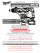
CATALOG NO. 2718-20
REVISED BULLETIN
SPECIFY CATALOG NO. AND SERIAL NO. WHEN ORDERING PARTS
M18™ FUEL™ 1-3/4” SDS-Max Rotary Hammer with One-Key™
STARTING
SERIAL
DATE
Feb. 2019
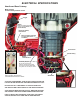
WIRING INSTRUCTION
J97A
EXAMPLE:
Component Parts (Small #)
Are Included When Ordering
The Assembly (Large #).
0
00
SEE PAGE 4
l= Component of the
14-46-2718 Service
Maintenance Kit
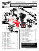
• See page 2 for the exploded view and parts listing of the
mechanicalportionofthetoolandservicextures.
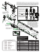
• See page 3 for lubrication instructions, torques chart,
maintenance instructions and service kits.
• See Page 4 for wiring instructions.
FIG. PART NO. DESCRIPTION OF PART NO. REQ.
48a --------------- Housing Halve Cover (1)
48b --------------- Housing Halve Support (1)
48c 06-82-2025 M3.5 x 16mm Pan Hd. Plastite T-10 Screw (2)
48d 05-78-5311 M5 x 18mm Pan Hd. ST T-20 Screw (15)
49 43-62-0038 Handle Kit (1)
49a --------------- Handle Support (1)
49b --------------- Handle Cover (1)
49c 44-66-0057 Auto Stop Plate (1)
49d 44-06-0014 Bluetooth Indicator Lens (1)
49e 44-06-0018 Bluetooth Working Lens (1)
49f 42-42-0054 Foam Bushing (3)
50 31-21-0066 Coin Cell Cover Kit (1)
50a --------------- Coin Cell Cover (1)
50b 05-81-1100 M2.6 x 6mm ST Phillips Screw (2)
51 23-66-5027 On-O Switch (1)
52 45-72-0012 Switch Trigger (1)
53 40-50-0059 Spring (1)
54 40-50-0027 Spring Plate (1)
55 44-60-0089 Lock Button (1)
57 --------------- 3V Coin Cell Battery (CR2032H) (1)
62 12-20-0138 Service Nameplate (1)
22e
22f
NOTE:
When servicing,
tool, Do Not
attempt to
disassemble
Electronics
Assembly (46).
See Page 1.
49b
48d
(6x)
50a
50b
(2x)
49f
(3x)
39h
51
55
54
53
49a
48d
52
49d
49c
49e
48d
(9x)
62
43
44
48b
45
47
(4x)
46f
42
48a
57
48c
(2x)
48a 48b 48c
48d 62
48
50a
50b
50
48d 49a 49b 49c
49d 49e 49f 50
49
41
21a 21b 21c 21d 21e 21f 21g
21h 21j 21k 21m 21n 21p 21q
21
21q
21p
21n
21m
21k
21j
21h
21e
21d
21f
21g
21e
21c
21a
21b
46f
46
22e
22f
22
46f
l
l
Place foam pads on
bottom of PCB boat as shown.
FIG. PART NO. DESCRIPTION OF PART NO. REQ.
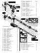
21 42-62-0013 Side Handle Assembly (1)
21a 05-89-0015 Fixing Screw (1)
21b 45-88-0103 Flat Washer (1)
21c 43-72-0002 Holder 1 (1)
21d 43-72-0003 Holder 2 (1)
21e 06-55-0018 Hex Nut (1)
21f 31-05-0011 Clamping Ring (1)
21g 44-66-0049 Support Plate (1)
21h 44-90-0046 Ring (1)
21j 43-76-0012 Absorber Housing (2)
21k 44-52-0013 Absorber (1)
21m 43-87-0015 Bellows (1)
21n 43-24-0010 Extension (1)
21p 42-52-0031 Side Handle Cap (1)
21q 43-98-5316 Side Handle (1)
22 14-29-0013 Gearcase Assembly (1)
22e --------------- Flat Washer (1)
22f --------------- M6 x 10mm BUH Hex Recess Screw (1)
39h 06-82-0032 M4 x 12mm Pan Hd. ST T-20 Screw (1)
41 44-50-0013 Lock Cam (1)
42 34-40-5308 O-Ring (1)
43 34-40-0088 O-Ring (1)
44 42-70-0028 EM-Clutch Assembly (1)
45 16-01-0010 Rotor Assembly (1)
46 --------------- Electronics Assembly (1)
46f 44-52-0066 Foam Pad (Set of two) (1)
47 05-88-0028 M6 x 55mm Pan Hd. Taptite T-30 Screw (4)
48 31-44-0118 Housing Assembly (1)