
Service Parts List S/N J97A
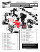
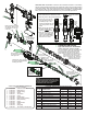
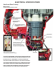

FIG. PART NO. DESCRIPTION OF PART NO. REQ.
23 02-50-0018 Needle Bearing (2)
24 45-88-0074 Washer (1)
25 32-10-0012 Clutch Assembly (1)
26 45-88-5327 Washer (1)
27 02-50-5315 Needle Bearing (2)
28 32-62-0010 Crank Shaft (1)
29 32-05-0016 Spindle Bevel Gear (1)
30 42-76-0014 Drive Sleeve (1)
31 44-66-0048 Locking Plate (1)
32 14-09-0012 Piston and Connecting Rod Assembly (1)
32a --------------- Wrist Pin (1)
32b --------------- Piston (1)
32c 44-94-0016 Connecting Rod (1)
33 43-44-0012 Rubber Gasket (1)
34 05-78-5313 M4 x 14mm Pan Hd. Taptite T-20 (2)
35 42-36-0024 Selector Bracket Clamp Plate (1)
36 14-46-0100 Fork Assembly (1)
36a --------------- Fork (1)
36b --------------- Fork Assembly Spring (1)
37 31-15-0037 Gearcase Cover Kit (1)
37a 31-15-0028 Gearcase Cover (1)
37b 40-50-0149 Spring (1)
37c 43-56-0011 Spring Carrier (1)
38 05-78-5315 M5 x 33mm Pan Hd. Taptite T-25 Screw (6)
39 23-66-0071 Selector Knob Assembly (1)
39a 31-53-0010 Rubber Plug (1)
FIG. PART NO. DESCRIPTION OF PART NO. REQ.
39b 40-50-5320 Spring (1)
39c 34-40-5309 O-Ring (1)
39d 44-60-0067 Selector Knob with Knob Pin Insert (1)
39e 44-20-0018 Chisel Lock Arm (1)
39f 43-44-0014 Selector Knob Gasket (1)
39g 43-56-0012 Selector Guide (1)
39h 06-82-0032 M4 x 12mm Pan Hd. ST T-20 Screw (2)
39j 43-98-0014 Selector Knob (1)
39k 31-53-0011 Felt Plug (1)
40 44-94-0014 Lock Rod (1)
41 42-50-0013 Lock Cam (1)
50-08-5317 Bit Grease (1)
FIG. PART NO. DESCRIPTION OF PART NO. REQ.
1 45-12-5316 Rubber Dust Shield (1)
2 45-22-5317 Front Latch Sleeve (1)
3 34-60-5316 Retaining Ring (1)
4 45-88-5316 Washer (1)
5 34-40-5316 Spindle O-Ring (2)
6 45-88-5321 Washer (1)
7 45-22-5319 Sliding Collar (1)
8 45-22-5321 Locking Sleeve (1)
9 45-88-5371 Washer (1)
10 44-66-5316 Front Spring Retainer (1)
11 40-50-5318 Spring (1)
12 44-66-5314 Rear Spring Retainer (1)
13 34-40-5315 Retaining Ring (1)
14 14-46-0099 Bearing Shield Assembly (1)
14a --------------- Bearing Shield (1)
14b 34-40-5321 O-Ring (2)
14c 45-06-5170 Felt Seal (1)
14d 45-06-0012 Rotary Seal (1)
14e 02-50-5316 Bearing Ring (1)
15 45-88-5323 O-Ring (1)
16 44-20-5316 Key (2)
17 38-50-0012 SDS-Max Spindle Assembly (1)
17a 44-82-5317 SDS-Max Spindle (1)
17b 44-90-0037 Brake Ring (1)
17c 44-90-0039 Rebound Ring (2)
17d 34-60-0072 Back Press Ring (1)
17e 44-60-5316 Spindle Sleeve Pin (6)
17f 44-90-5317 Steel Ring (1)
17g 44-90-5319 Spring Ring (1)
17h 45-22-0013 Barrel (1)
18 42-06-0028 Anvil Assembly (1)
18a --------------- Anvil (1)
18b 34-60-5319 O-Ring (2)
18c 45-06-5317 Turcon Seal (2)
19 45-56-0018 Striker Assembly (1)
19a 45-22-0016 Striker (1)
19b 34-40-0078 O-Ring (2)
20 45-88-0073 Washer (1)
22 14-29-0013 Gearcase Assembly (1)
l= Component of the 14-46-2718
Service Maintenance Kit
36a
36b
36
18a 18b
18c
18
7
1
2
3
4
5
6
15
14e
14d
14c
14b
14a
25
20
19b
19a
16
17a
17b
18a
18b
18c
17c
17d
17c
17e
17f
17g
17h
37b
37c
36b
36a
35
34
32a
38 (6x)
37a
33
17a 17b 17c 17d 17e
17f 17g 17h 18
17
19a
19b
19
29
30
31
19b
32b
32c
28
27
26
19b 32a
32b 32c
32
37a 37b
37c
37
39h
41
40
39e
39d
39c
39b
39j
39g
39f
39k
39a
39a 39b 39c 39d 39e 39f
39g 39h 39j 39k 40 41
39
22
24
23
17h 20
Washer
#20 is to be
located here on
barrel #17h
17c
Position
tapered side
of rebound rings
#17c to face striker #19
and anvil #18 as shown
14a 14b 14c
14d 14e
14
9
8
12
11
10
13
14a
24
14a (Back side)
Be sure to orient front notches of bearing shield
#14a at the 12:00/6:00 position or at the 9:00/3:00
position prior to installing in gearcase #22. Doing
so will allow tabs in rear of bearing shield to
seat in corresponding notches in gear
case cavity. This must be done to
allow for proper seating of
retaining ring #13.
l
l
l
l
l
l
l
l
l
l
l