
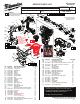
Service Parts List


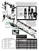


Pack the rear of the piston
with grease. There is to be
no lubrication on the face
of the part.
Place 6-5/16 oz. (180g)
of grease in the bottom
of the gearcase
Place 5/8 oz. (18g) of grease
in the rear of the barrel before
installing the striker
Coat the inside
of the spindle driver
prior to assembly
Coat teeth of
clutch assembly
with grease
Coat o-ring and
o-ring groove prior
to installing o-ring.
With o-ring
installed, coat around
entire side of ram
17h 20
Washer
#20 is to be
located here on
barrel #17h
Fig. 1
Small
hole in
barrel
1. Place washer #20 onto backside of barrel.
2. Place 18 grams of ‘Q2’ grease inside barrel.
3. Coat o-ring groove on ram
and o-ring with grease prior
to installing o-ring on ram.
Coat the assembled ram and
o-ring with grease as shown
below.
4. When placing ram assembly
into barrel, slowly apply
pressure to ram assembly.
5. Push the ram assembly until
rear face is just below small
hole in the barrel. DO NOT
wipe off any excess grease
that oozes out of holes.
No grease on rear
face of ram (striker)
#19a
Washer
#20
2
5
5
1
4
3
LUBRICATION NOTES:
Type ‘Q2’ Grease, No. 49-08-5355
(2.8oz, 80g tube) 3 tubes needed
Prior to reinstalling, clean gear assemblies with
a clean, dry cloth. Lightly coat all individual
parts highlighted here with grease. Apply a
greater amount of grease to all internal and
external gear teeth. Place 18 grams
of grease in the rear of the barrel
prior to inserting the ram. Place the
remaining grease in the
bottom of the gearcase.
Lubrication Note: MILWAUKEE recommends that scheduled maintenance of this Rotary
Hammer include lubrication replacement, and replacement of vital O-rings and gaskets at each
carbon brush change. Doing so will prolong the life of the hammer by reducing wear to gears
and mechanism parts. The carbon brushes and armature commutator in this MILWAUKEE
Rotary Hammer are designed and matched for many hours of reliable performance.
l
14-46-2718 MAINTENANCE SERVICE KIT
THIS KIT CONTAINS:
1 45-12-5316 Rubber Dust Shield
1 34-60-5316 Retaining Ring
2 34-40-5316 Spindle O-Ring
2 34-60-5319 O-Ring
2 45-06-5317 Turcon Seal
2 34-40-5308 O-Ring
2 42-42-0054 Foam Bushing
1 14-46-0099 Bearing Shield Assembly
1 34-60-0072 Back Press Ring
2 34-60-0078 O-Ring
1 43-44-0012 Rubber Gasket
1 34-40-5309 O-Ring
1 44-90-5319 Spring Ring
3 49-08-5355 ‘Q2’ Grease (2.8oz/80g tube)
FASTENER TORQUE SPECIFICATIONS (IN./LBS.)
SEATING TORQUE
FIG. NO. WHERE USED in/lbs kgf/cm Nm
34 Selector Bracket Clamp Plate 11 13 1.3
38 Gearcase Cover 63 73 7.2
47 Motor Housing 56 65 6.4
48d Housing Halve Cover 25 29 2.9
48c Housing Halve Cover 11 13 1.3
50b Coin Cell Cover 2.6 3.05 0.3
39h Selector Knob 16 18 1.8
39h On-O Switch 11 13 1.3
Switch Termination Screws 8 10 1.0
Ground Screw-Gearcase 44 50 5.0
NOTE:
Be sure that the shank of the bit is clean.
For best performance, be sure the shank
is lightly greased prior to installation.
Use Bit Grease No. 50-08-5317.