
Service Parts List S/N H98A

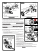

Components of Right Gearcase Kit #14-30-1033
Components of Left Gearcase Kit #14-30-1043
Aluminum Tape
Alignment Plug / Key
Right
Gearcase
Ball Bearing
Bearing Retainer
Right Helical Gear
Screws (3x)
Picture ‘A’
Picture ‘B’
Aluminum Tape
Alignment Plug / Key
Left Gearcase
Ball Bearing
Bearing Retainer
Left Helical Gear
Screws (3x)
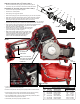
Drive Pin Sleeve
Spiral Gear
Keyway
not in-line with
Gearcase Keyway
FIG. 1
Gearcase
Keyway
Opening
FIG. 2
FIG. 3
Alignment Plug / Key
installed in
Gearcase
Right
Gearcase
14-30-1033
‘Shown’
Plug / Key from kit
Spiral Gear
Keyway
in-line with
Gearcase Keyway
Gearcase
Keyway
Opening
Picture “A and B” show the components that make-up the Right and Left Gearcase kits for
M18™ FUEL™ Hackzall
®
2719-20. Each kit contains one [1] Alignment Plug / Key and [1]
round Aluminum adhesive backed disc (not sold separately) which will be needed when ser-
vicing / replacing the gearcase assemblies of the M18™ FUEL™ Hackzall
®
.
The Right and Left helical gear assemblies are supported independently in their respective
gearcase assembly and turn independently. Each of the helical gears have a counter weight
and when the two gearcase halves are assembled together gearing must be synchronized
to eliminate excessive vibration.
Synchronization of the two gear case halves can be accomplished by using the Alignment
Plug / Key supplied with each gearcase kit. Anytime rotor assembly 16-01-0900 has to be
removed from the gearcase halves, helical gears will need to be resynchronized using the
alignment plug / keys.
Synchronizing / Assembling Gearcase Kit Assemblies 14-30-1033 – 14-30-1043
Once the rotor assembly has been removed from the gearcase assembly the keyway cut
into each helical gear will no longer be aligned with the gearcase keyway ( g. 1) due to the
counter balance of the helical gear.
1. Rotate (by hand) helical gear in right gearcase (picture “A”) until helical gear keyway is
in-line with the gearcase keyway (g. 2).
2. Install plug / key from kit into gearcase / helical gear keyway (g. 3).
3. Install drive pin sleeve onto pin located on right helical gear (coat with type “L” grease).
FIG. 4
With pinion of Rotor Assembly secured in
Gear Case Kits, remove and save Alignment
Plug/Keys. Apply Aluminum Tape from kits as
shown. Stator of the Electronic Assembly is than
carefully placed over Rotor Assembly. Stator/Rotor
Assemblies are captured
in Motor Insulator halves
and secured with
fasteners.
4. Install spindle / gearcase
bushing assembly into right
gearcase (coat components with
type “L” grease and make sure
spindle lock pin hole faces right
gearcase).
Note: If new felt seal is being
installed saturate seal with a
lightweight oil.
5. Place approximately 1/8oz. Type
“L” grease onto teeth of right
helical gear. (Set assembly aside).
6. Rotate (by hand) helical gear in left gearcase (picture “B”) until helical gear keyway is
in-line with the gearcase keyway (g. 2).
7. Install plug / key from kit into gearcase / helical gear keyway (g. 3).
8. Place approximately 1/8oz. Type “L” grease onto teeth of left helical gear.
9. Assemble lubricated left gearcase assembly onto lubricated right gearcase assembly and
install ve [5] gearcase screws.
10. Install rotor assembly 16-01-0900 and secure to gearcase assembly.
11. Remove left and right alignment plug (s) and apply aluminum tape disc from kits to each
side of gearcase (g.4). SAVE PLUGS in case rotor needs servicing or replacing.