
Service Parts List S/N H98A

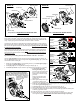

Ground Wire Terminal
is secured to the other
side of gear case
= Wire Traps
LED Assembly
On-Off Switch
Potted PCBA
Battery Connector Block
Rotor, Stator and Hall Board
are captured inside Motor
Insulator Kit.
LED
Assembly
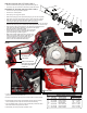
4. Install spindle / gearcase
bushing assembly into right
gearcase (coat components with
type “L” grease and make sure
spindle lock pin hole faces right
gearcase).
Note: If new felt seal is being
installed saturate seal with a
lightweight oil.
5. Place approximately 1/8oz. Type
“L” grease onto teeth of right
helical gear. (Set assembly aside).
6. Rotate (by hand) helical gear in left gearcase (picture “B”) until helical gear keyway is
in-line with the gearcase keyway (g. 2).
7. Install plug / key from kit into gearcase / helical gear keyway (g. 3).
8. Place approximately 1/8oz. Type “L” grease onto teeth of left helical gear.
9. Assemble lubricated left gearcase assembly onto lubricated right gearcase assembly and
install ve [5] gearcase screws.
10. Install rotor assembly 16-01-0900 and secure to gearcase assembly.
11. Remove left and right alignment plug (s) and apply aluminum tape disc from kits to each
side of gearcase (g.4). SAVE PLUGS in case rotor needs servicing or replacing.
3m
3c
3g
3f
3e
3d
3b
3a
Leg
Inner Slot
3
3a 3b 3c 3d
3e 3f 3g
REMOVING THE STEEL QUIK-LOK
®
BLADE CLAMP (3)
• Remove external retaining ring (3a) and pull front cam (3b) off.
• Pull lock pin (3c) out and remove remainder of parts and discard.
REASSEMBLY OF THE STEEL QUIK-LOK
®
BLADE CLAMP (3)
• Coat new lock pin with powdered graphite.
• Hold tool in a vertical position.
• Place spring cover (3g) onto spindle.
• Slide torsion spring (3f) onto spindle with spring leg on hole side of spindle.
• Slide sleeve (3e) onto spindle aligning hole on sleeve with hole in spindle.
• Slide rear cam (3d) over sleeve (3e) until it bottoms on sleeve shoulder,
ensure leg of spring (3f) inserts into inner slot in rear cam (3d).
• Rotate rear cam in the direction of the arrows located on spring cover until there is
clearance for lock pin (3c) to be inserted into sleeve/spindle holes. Insert lock pin.
• Align front cam (3b) inner ribs with rear cam outer slots and slide front cam
onto sleeve until it bottoms. Retaining ring groove on the spindle
shaft (3m) should be completely visible.
• Attach retaining ring (3a) by separating coils and inserting
end of ring into groove, then wind remainder of ring into
groove. Ensure ring is seated in groove.
• Blade clamp should rotate freely. During normal usage,
debris may not allow blade clamp to rotate freely. The
use of spray lubricant can help free blade clamp. In
extreme conditions, follow these instructions to
remove, clean and reassemble blade clamp.
SCREW TORQUE SPECIFICATIONS
SEAT TORQUE
FIG. PART NO. WHERE USED (KG/CM) (IN/LBS)
2 05-74-0985 Shoe Assembly 18-24 15.6-20.8
2 05-74-0985 Motor Insulator 18-24 15.6-20.8
4 06-82-2025 Housing Cover 5-8 4.3-6.9
6e --------------- Bearing Plate 14-18 12.1-15.6
8 06-82-5320 Gear Case-Left 36-42 31.2-36.4
10 05-78-0105 Rotor Assembly 24-30 20.8-26.0
13 06-82-1080 Motor Insulator 12-18 10.4-15.6
WIRING
§As an aid to reassembly, take note of wire routings and position in wire
guides and traps while dismantling tool.
§ Be sure all components are rmly and squarely seated in handle cavities.
§ Be careful and avoid pinching wires between housing halves by tucking
wires completely down in traps and channels when assembling.
§ Prior to installing battery, check for proper functionality of switches, slides
and buttons after housing halves are secure.
§ Install battery and verify the proper operation of tool.