
Service Parts List


MILWAUKEE TOOL l www.milwaukeetool.com
13135 W. Lisbon Road, Brookeld, WI 53005
Drwg. 1
BULLETIN NO.
54-40-2740
SERVICE PARTS LIST
FIG. PART NO. DESCRIPTION OF PART NO. REQ.
1 45-16-0927 Shoe/Water Barrier Assembly (1)
2 06-82-5320 8-32 x 5/8" Pan Hd. Tapt. T-20 Screw (2)
3 14-46-1011 Steel Quik-Lok
®
Blade Clamp Kit (1)
3a 34-60-3680 Retaining Ring (1)
3b 42-50-0076 Front Cam (1)
3c 44-60-0626 Lock Pin (1)
3d 42-50-0077 Rear Cam (1)
3e 45-22-0081 Sleeve (1)
3f 40-50-0161 Torsion Spring (1)
3g 31-15-0511 Spring Cover (1)
3h 44-86-0740 Front Cap (1)
3j 45-06-0880 Felt Seal (1)
3k --------------- Spindle Bushing (1)
3m --------------- Spindle Shaft (1)
4 06-82-2025 M3.5 x 16mm Pan Hd. Plast. T-10 Scr. (10)
5 31-44-2719 Housing Kit (1)
5a --------------- Housing Cover - Right Housing (1)
5b --------------- Housing Support - Left Housing (1)
6 14-30-1033 Right Gear Case Kit (1)
6a 23-70-3350 Aluminum Tape (2)
6b --------------- Gear Case - Right (1)
6c --------------- Ball Bearing (2)
6d --------------- Bearing Plate (2)
6e --------------- Bearing Plate Screw (6)
6f --------------- Spiral Beval Gear (1)
6g 44-86-0803 Drive Pin Sleeve (1)
7 14-30-1043 Left Gear Case Kit (1)
7a --------------- Spiral Bevel Gear (1)
7b --------------- Gear Case - Left (1)
8 06-82-5320 8-32 x 5/8 Pan Hd Slt. T-20 Screw (7)
CATALOG NO. 2719-20
REVISED BULLETIN
SPECIFY CATALOG NO. AND SERIAL NO. WHEN ORDERING PARTS
M18™ FUEL™ HACKZALL
®
Reciprocating Saw
STARTING
SERIAL NO.
DATE
July 2017
WIRING INSTRUCTION
H98A
EXAMPLE:
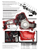
Component Parts (Small #) Are Included
When Ordering The Assembly (Large #).
0
00
SEE PAGE 3
FIG. LUBRICATION
(Type 'L' Grease, No. 49-08-4175):
3h,3j Saturate Felt (3j) with lightweight oil prior to assembly with
Cap (3h) onto Bushing (3k) and Spindle (3m).
3k,3m Lightly coat the O.D. of Spindle Shaft (3m) and I.D. of Bush
ing (3k) with grease.
3m Place a dab of grease in the rear slot of Spindle Shaft (3m).
6b,7b Place .25 ounce grease in gear cavity of Gear Cases (6b,7b).
Coat the spindle shaft pocket in Gear Cases (6b,7b).
6f,6g Lightly coat the Drive Pin of Spiral Bevel Gear (6f) and I.D.
and O.D. of Bearing Sleeve (6g) with grease.
6f,7a,9 Completely coat all of the teeth of the Spiral Bevel Pinion
on Rotor (9) and Spiral Bevel Gears (6f,7a) with grease.
FIG. PART NO. DESCRIPTION OF PART NO. REQ.
9 16-01-0900 Rotor Assembly (1)
10 05-78-0105 M4 x 10mm Pan Hd. Taptite T-20 Scr (2)
12 31-50-1155 Motor Insulator Kit (1)
12a --------------- Motor Insulator Halve - Right (1)
12b --------------- Motor Insulator Halve - Left (1)
13 06-82-1050 4-20 x 0.76 Pan Hd. ST T-10 Screw (6)
14 40-50-1090 Terminal Block Spring (1)
15 14-20-2719 Electronic Assembly (1)
16 45-24-0682 Locking Shuttle (1)
17 05-74-0985 M4 x 12mmPan Hd. Tapt. T-20 Screw (4)
20 12-20-1119 Service Nameplate (1)
31 38-50-0415 Spindle/Bushing Kit (1)
40 50-55-3560 M18 FUEL Contractor Bag (1)
50 31-53-0280 Alignment Plug - Service Tool
(Not component of tool - one per in kits 6 & 7)
3g
3e
3b
3a
3f
3d
8
(2x)
6g
6e
(3x)
3m
3c
3k
3j
3h
4
(10x)
5a
20
6a
6c
6d
6e
(3x)
6f
7a
10
(2x)
6d
6c
7b
6b
16
6a
8
(5x)
5b
12a
15
12b
13
(6x)
14
9
17
(4x)
6
6a 6b 6c 6d
6e 6f 6g 50
3
3a 3b 3c 3d
3e 3f 3g
31
3h 3j
3k 3m
7
6a 6c 6d 6e
7a 7b 50
12
17 12a
12b 13
5
4 5a
5b 20
NOTE:
Clean Gear Case
Kits (6 and 7) with
a clean, dry cloth.
DO NOT wash up.
NOTE:
Lock Pin (3c) to
be coated with
graphite prior to
assembly.
50
Alignment Plugs- For Service Only
Plugs are furnished in Gear Case Kits
#6 and #7. Plugs are not components
of the tool. DO NOT DISCARD after
use. Save for other possible
service applications.
1
8
40