
Use and Care Manual


4
ASSEMBLY
WARNING
Recharge only with the charger
specied for the battery. For spe-
cic charging instructions, read the operator’s
manual supplied with your charger and battery.
Removing/Inserting the Battery
To remove the battery, push in the release buttons
and pull the battery pack away from the tool.
WARNING
Always remove battery pack before
changing or removing accessories.
To insert the battery, slide the pack into the body
of the tool. Make sure it latches securely into place.
WARNING
Only use accessories specically
recommended for this tool. Others
may be hazardous.
Always remove battery from tool before changing
or removing accessories. Only use accessories
specically recommended for this tool. Others
may be hazardous.
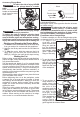
Installing Collets
The collet must be attached to the collet nut before
installing the collet assembly to the tool. Be sure
that the collet size matches the size of the bit shank,
otherwise the collet may break.
1. To assemble, place collet on an even surface, and
place the nut over the collet.
2. Press down on the nut to snap the nut and collet
together.
3. To disassemble, use a rod to push the collet out
of the nut.
Installing/Removing Bits
WARNING
Always remove battery from the
tool before attaching or removing
accessories or making adjustments.
Use only specically recommended accessories.
Others may be hazardous.
Never use bits larger than the smallest of the
openings in the base, sub-base, or dust shroud.
The use of larger bits can result in loss of control
and possible serious personal injury.
Do not tighten the collet nut without inserting the
bit. The collet may break.
Never touch the bit during or immediately after
use. After use the bit, collet, and collet nut may
be hot enough to burn bare skin.
1. Turn the On/O switch to OFF (O) and remove
the battery pack.
2. Place the router upside down on a workbench.
3. Press and hold the spindle lock and use the 11/16"
wrench to loosen the collet nut counterclockwise
(or use the 7/16" spindle lock wrench to hold the
spindle securely).
4. Insert the bit shank into the collet as far as it will go.
5. Back the bit shank out slightly to avoid bottoming
out.
6. Be sure there is a
Minimum
1/16"
Bit
shank
Collet
Collet nut
minimum of 1/16"
between the bot-
tom of the collet
assembly and the
radius to the cut-
ting portion of the
bit.
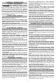
FUNCTIONAL DESCRIPTION
1. ON/OFF switch
2. Speed control dial
3. Collet / collet nut
4. LED (not shown)
5. Spindle lock
6. Micro adjustment
dial
7. Quick release
lever
8. Macro adjustment
button
9. Gripping surface
10. Depth turret
11. Micro adjustment
sleeve
12. Handles
13. Depth gauge knob
14. Plunge release
lever
15. Depth gauge
indicator
16. Depth gauge
17. Shaft / housing hole
Plunge base
14
16
10
11
7
Cat. No. 2723-20
5
4
3
2
1
Oset base
17
Fixed base
7
9
6
8
13
9
7
15
12
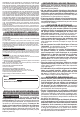
SYMBOLOGY
Volts
Direct Current
No Load Revolutions per Minute (RPM)
Read Operator's Manual
C
US
UL Listing for Canada and U.S.