
Use and Care Manual


6
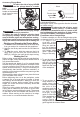
12.
Rotate the collet nut to
Shaft and
housing
hole
Output
shaft
align the output shaft
hole with the housing
hole. Insert the 3 mm
hex wrench through
both the output shaft
and housing.
13. Use the 11/16" wrench
Collet
nut
to securely tighten the
collet nut clockwise.
14. To remove the base,
reverse the procedure.
WARNING
During use, always keep vacuum
hose clear of the path of the bit.
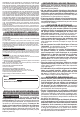
Installing a Dust Shroud
Fixed Base
1. Attach the dust shroud
Thumb
screw
to the xed base, and
tighten the thumb
screw.
2. Connect a vacuum
hose to the port.
WARNING
To reduce the risk of injury, do not
use the dust shroud when plunge
cutting if the bit is larger than the port opening
(1-3/8"). If a rotating router bit contacts the dust
shroud, the adapter will break and ying debris
may cause injury.
Accessory Plunge Base
1. Attach the dust shroud
Thumb
screws
to the plunge base,
and slide the U-rod
into the base holes.
2. Tighten the thumb
screws.
3. Connect a vacuum
hose to the port.
Installing a Straight Edge Guide
The straight edge guide is for use with the xed base.
1. Assemble the
Edge guide
screw
Wing nut
straight edge guide,
as shown.
2. Attach the straight
Clamp
screw
edge guide to the
fixed base and
tighten the clamp
screw securely.
Template Guides
Use only a maximum 1-3/16" template guide with this
tool. A 5-3/4" template sub-base plate is needed to
install a template guide. Always use a centering cone
for best results with a 1-3/16" center hole.
To install a template guide, insert the guide into the
center hole of the subbase and secure according to
the template guide instructions.
OPERATION
WARNING
To reduce the risk of injury, always
wear proper eye protection marked
to comply with ANSI Z87.1.
When working in dusty situations, wear appro-
priate respiratory protection or use an OSHA
compliant dust extraction solution.
Remove the battery before changing accessories
or making adjustments.
Never make adjustments while the router is
running.
DO NOT use the router if the quick release lever
does not hold the motor securely in the base.
NEVER use the plunge base in a router table.
Selecting the Speed
The (RPM) of tool can be changed by turning the
speed control dial. Variable speed dial settings range
from numbers six (6) through one (1). Higher num-
bers correspond to higher speeds and lower number
correspond to lower speeds.
Use higher speeds for smaller bits and cutters, soft-
woods, plastics and laminates.
Use lower speeds for larger diameter bits and cutters.