
Product Manual

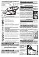
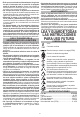


Battery Connector Block
On-Off Switch
Trigger
Tuck excess
lead wire here
Hi-Low Button
Assembly
PCBA
Wires to
Stator
Assembly
WIRING INSTRUCTIONS
As an aid to reassembly, take notice of wire routing and position in wire guides and traps while
dismantling tool. Be careful and avoid pinching wires between handle halves when assembling.
• Place PCBA and the On-O Switch of Electronics Assembly (46) squarely and rmly in place
in the corresponding Housing Support (29) cavities.
• Route wires from the Switch and PCBA as shown, tucking the wires down into wire traps.
• Install Battery Connector Block squarely and rmly into Housing Support. Route wires
through Housing Support channel (removing any slack along the way). Be sure wires are pushed
down into the wire traps. Place excess wires in housing cavity as shown.
• Install the Hi-Low Button and route wires as shown. Be sure wires are pushed down completely in
traps and channels.
• Place Cone Section (2) onto Bell Tube (14), place squarely into Housing Support (29) and secure
with 6 Screws (13).
• Be sure the Trigger (23), Spring (25), Cushion (24)
and Lock Button (26) are properly in place.
• Be sure the Nozzle Lock and Nozzle Lock Spring
(27 and 28) are in place.
• Secure housing halves together using 12 Screws (13)
on the cover side and 1 Screw on the support side.
• Check for the proper functionality of the Switch Trigger
(23) and Lock Button (26).
• Insert battery pack and check tool for proper operation.
NOTE:
There is a PCBA wire
with a tabbed washer
that must be placed
over rotor bearing
and captured in
Motor Insulator
(42).