
Service Parts List S/N J72A
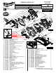

M18 FUEL™ HP 7-1/4" Circular Saw
2732-20 J72A
54-40-2790
See Page Three
FIG. PART NO. DESCRIPTION OF PART NO. REQ.
1 06-75-1012 Blade Screw 1
2 43-34-0795 Outer Blade Flange 1
5 05-78-1005 M3.5 x 12mm Pan Hd. Phillips Machine Screw 1
6 49-90-4001 Dust Chute (Accessory) 1
7 05-78-5316 M4 x 14mm Pan Hd. Taptite T-20 Screw 3
9 43-34-0790 Inner Blade Flange 1
11 34-60-0860 Retaining Ring 1
12 28-41-1001 Lower Guard 1
13 06-82-5314 10-24 x 1/2" Pan Hd. Tapt. T-25 Screw 2
14 44-10-1008 Lower Guard Lever 1
15 40-50-0045 Lower Guard Spring 1
16 45-04-0485 10-32 x 13/16" Bumper Screw 1
17 42-38-0222 Rubber Bumper 1
18 06-82-5285 6-32 x 1/2" Pan Hd. ST T-15 Screw 13
19 31-15-6002 LED Cover 1
20 22-44-4140 LED Assembly 1
21 44-46-9001 Retaining Plate 1
22 45-14-0015 Spindle Hub Sleeve 1
27 06-75-5860 1/4-20 x 3/4" Hex Head Bolt 1
29 44-60-0741 Pivot Pin 1
30 45-06-0720 Felt Seal 1
31 40-50-8046 Spindle Lock Spring 1
32 44-20-1001 Spindle Lock 1
33 28-14-7004 Upper Guard Gear Case with Needle Bearing 1
34 42-42-1030 Spindle Lock Button 1
35 06-10-0110 M6 x 28mm Carriage Bolt 1
36 45-88-1560 Washer 1
37 43-98-0705 Bevel Adjustment Knob 1
38 --------------- Shoe Assembly 1
40 40-50-0650 Rip Fence Spring 1
41 43-98-0605 Rip Fence Knob 1
42 34-40-8001 O-Ring 1
46 05-74-1030 M5 x 8mm Pan Hd. Taptite T-25 Screw 2
51 22-56-0150 Closed End Connector (See Wiring Diagram) 1
52 23-94-2731 High Voltage Wire Assy. (See Wiring Diagram) 1
55 31-44-7002 Handle/Housing Halve - Right 1
56 23-66-5027 On-OSwitch 1
57 42-42-0345 Lock-OButton 1
58 40-50-1760 Lock-OButtonSpring 1
59 34-40-4480 O-Ring 1
60 05-78-1010 M3.5 x 12mm Pan Hd. T-10 Machine Screw 4
61 31-44-6002 Handle/Housing Halve - Left 1
62 45-88-1515 Washer 1
63 45-08-0395 Depth Shaft 1
REVISED BULLETIN
SERVICE PARTS LIST
BULLETIN NO.
WIRING INSTRUCTION
DATE
SPECIFY CATALOG NO. AND SERIAL NO. WHEN ORDERING PARTS
CATALOG NO.
MILWAUKEE TOOL
l
www.milwaukeetool.com
13135W.LisbonRd.,Brookeld,WI53005
Drwg. 1
STARTING
SERIAL NO.
EXAMPLE:
Component Parts (Small #) Are Included
When Ordering The Assembly (Large #).
0
00
June 2018
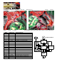
SEE PAGE 2 FOR SERVICE
NOTES AND LUBRICATION
OF THIS TOOL
93
77
77a
6
5
86
13
14
12
15
21
22
85
18
(2x)
33
27
34
42
19
18
(3x)
18
(4x)
16
17
30
31
32
29
9
2
1
11
7
(3x)
18
(4x)
80
20
62
63
59
55
46
(2x)
81
58
61
57
56
72
(2x)
65
(10x)
64
13
66
40
41
35
37
36
38
68
(2x)
70
71
67
69
67 68 69
70 71 72
83
55 59 61
65 90 91
82
60
(4x)
35 36 37 38 40
41 90 91 92 94
84
90
94
(4x)
9192
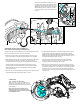
WARNING:
Magnetic force is
VERY STRONG when
installing rotor into stator.
Extreme care must be taken
to prevent damage to tool and
personal injury. Do not have fingers
in front of rotor fan!
FIG. PART NO. DESCRIPTION OF PART NO. REQ.
64 44-10-0018 Depth Lever 1
65 06-82-7470 6 x 11/16" Pan Hd. Plastite T-15 Screw 10
66 49-96-0600 Hex Key 1
67 43-74-0065 Rafter Hook Bar 1
68 44-60-0585 Coil Pin 2
69 45-22-1005 Detent Sleeve 1
70 40-50-0985 Spring 1
71 43-74-8001 Rafter Hook Housing 1
72 06-82-0052 M6 x 32mm Pan Hd. PT T-25 Screw 2
75 05-81-1195 M3 x 8mm Pan Hd. ST T-10 Screw 2
77 49-90-3001 Dust Adapter (Standard Equipment) 1
77a 49-90-3002 Dust Adapter (Optional) 1
80 14-20-7007 Electronics Assembly 1
81 16-01-7009 Rotor Assembly 1
82 14-38-7008 Handle/Housing Kit 1
83 14-34-7006 Rafter Hook Assembly 1
84 14-74-7005 Shoe Assembly 1
85 38-50-7003 Output Shaft Assembly 1
86 28-20-7002 Upper Guard Cover Assembly 1
87 12-20-8397 Service Nameplate (Not Shown) 1
88 10-20-2032 Warning Label (Not Shown) 1
89 49-22-2731 Rip Fence (Not Shown) 1
90 31-51-0137 Bevel Scale 1
91 31-51-0132 Front Scale 1
92 06-83-1600 Set Screw 1
93 42-55-2743 Medium FUEL Contractor Bag 1
94 06-81-0015 M2.5 x 3.175 Phillips Screw 4