
Service Parts List S/N J72A
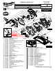

ASSEMBLING OUTPUT SHAFT ASSEMBLY (85)
INTO UPPER GUARD GEARCASE ASSEMBLY (33)
To prevent damage to the Felt Seal (30) it is recommended to temporarily
remove the felt seal until steps 1 and 2 are completed.
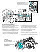
1. With the use of both hands, compress the Spindle Lock Spring (31)
back on the Spindle Lock Plate (32) past the small hole on the plate.
2. While holding the spring back with one hand, quickly insert a thin metal
instrument into the small hole on the plate. The metal instrument
should capture the entire spring (all coils should be behind that tool).
With the spindle lock spring trapped behind the small hole on the
spindle lock plate, slide the felt seal back onto the spindle lock plate.
Position the felt seal above the corresponding cavity in the Upper
Guard Gearcase (33).
3. Insert the open end of the spindle lock plate (32) into the opening of the
Output Shaft Assembly (85) behind the gear, as shown.
4. Insert the bearing shaft portion of the output shaft assembly into the
needle bearing of the upper guard gearcase assembly. Carefully
wiggle the entire output shaft assembly until the gearing of the output
shaft assembly engages with the pinion gearing of the Rotor (81) and
the output shaft assembly slides into place.
Secure the output shaft assembly to the upper guard gearcase
assembly with the use of four screws (18), not shown. It is recom-
mended to alternate the tightening of the screws.
5. Remove the thin metal instrument. Check for the proper functioning
of the spindle locking mechanism. Rotate the spindle shaft and depress
the Spindle Lock Button (34) at the same time. The spindle lock plate
should drop into one of four cogs that lock the spindle. Spindle lock
mechanism must return briskly when released from engagement in the
lock block cog.
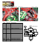
Detail 'A' shows Spindle Lock Spring (31) and
Felt Seal (30) in place in the respective cavities
of the Upper Guard Gearcase Assembly (33).
NOTE: The spindle hub and gear of the Output
Shaft Assembly (85) are not shown for clarity,
so the four Locking Cogs of the Lock Block can
be seen.
Detail 'A'
81
33
2
1
4
5
3
85 33 81 30 31 32 34
34
32
31
30
Locking Cogs
(behind gear)
LUBRICATION
Type 'J' Grease, No. 49-08-4220
Apply 3.0 grams (.10 oz) of 'J' Grease to the
gear bore in Upper Guard Gearcase (33). The
grease should be directed toward the pinion end
of the rotor (81).
When servicing, remove 90-95% of the
existing grease prior to installing Type 'J'.
Original grease may be similar in color but
not compatible with 'J'.