
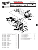
Service Parts List S/N J04A


6
LUBRICATION NOTES:
Type ‘Y’ Grease
No. 49-08-5270, 6oz. tube
When servicing the gears or the Gear Case,
90-95% of the old grease must be removed
prior to new grease being added. Clean gear
assemblies with a clean, dry cloth.
10
1
1
2
3
4
5
6
7
8
9
11
12
13
14
15
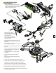
1. Apply a thin layer of grease
to the outside face (both sides)
and both inside bores at rear of
motor arm assembly.
2. Place a liberal amount of grease
on rotor pinion being sure to coat
all of the gear teeth.
3. Place a liberal amount of grease to the gear on
the spindle assembly being sure to coat all of the
gear teeth.
4. Place approximately 4.5 grams of grease in gear
cavity of motor arm assembly.
5. Brush surface of bevel axle with grease (both ends)
as shown.
6. Place a thin layer of grease to inside contact
surface and axle bore of arm hinge/slide rail
assembly (both sides).
7. Coat barrel of down lock pin with grease prior
to installation.
8. Place a light film of grease on both sides of
washers.
9. Apply a thin layer of grease to the entire shaft
of bevel stop pin.
10. Coat the inside contact surface of bevel arm with grease.
11. Coat the outside contact surface at the rear of table with grease.
12. Apply grease to the contact points of detent release trigger.
Add grease to front contact points and top surface of detent slider.
13. Place a dab of grease to the two raised catch tabs on detent spring.
14. Brush both sides of thrust bearing with a heavy layer of grease.
15. Coat all four washers with grease. Be sure to orient washers properly
prior to securing with table bolt.