
Use and Care Manual


5
7. Be sure that the collet is not clamped to a uted
section on the bit shank. The collet should be
clamped to a solid part on the bit shank to ensure
a tight grip.
8. Hand-tighten the collet nut.
9. Press and hold the spindle lock and use the 11/16"
wrench to securely tighten the collet nut clockwise
(or use the 7/16" spindle lock wrench to hold the
spindle securely).
WARNING
If the collet nut is not tightened
securely, the bit may come out
during use, causing serious personal injury.
Installing/Removing Bases
WARNING
To reduce the risk of injury, DO NOT
use the router if the quick release
lever does not hold the motor securely in the
base. If the quick release lever becomes loose,
secure the screw with a 3 mm hex wrench to make
a snug t.
Pressing the macro adjustment button will cause
the motor housing to drop down, which may
cause personal injury or damage to the tool or
workpiece. Make sure your hand is rmly on the
motor when pressing the button.
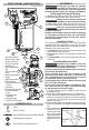
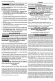
Fixed Base
1. Open the quick release
3
1
2
Macro
adjustment
button
lever. (1)
2. Press the macro adjust-
ment button on the xed
base. (2)
3.
Insert the tool into the
base. (3)
4.
Release the button.
5.
Close the quick release
lever.
6. To remove the base,
reverse the procedure.
Accessory Plunge Base
1. Open the quick release
2
1
lever. (1)
2. Insert the tool into the
base. (2)
3. Close the quick release
lever.
4. To remove the base,
reverse the procedure.
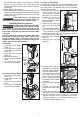
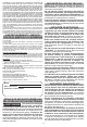
Accessory Oset Base
To install the oset base, the collet assembly must
be removed from the router motor and installed onto
the oset base. The transfer bit must be installed
onto the router motor.
1. Press and hold the spin-
Transfer
bit
Spindle
lock
dle lock and use the
11/16" wrench to loosen
the collet nut counter-
clockwise (or use the
7/16" spindle lock
wrench to hold the spin-
dle securely).
2. Remove the collet nut
and install the transfer
bit.
3. Press and hold the spin-
dle lock and use the
11/16" wrench to securely tighten the collet nut
clockwise (or use the 7/16" spindle lock wrench
to hold the spindle securely).
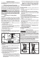
4. Open the quick release
1
2
lever. (1)
5. Insert the tool into the
base. (2)
6. Visually conrm that the
transfer bit is seated in-
side the pulley connec-
tion in the oset base.
7. If the transfer bit does
not align, remove the
motor from the offset
base, rotate the transfer
bit slightly, and reinstall
X
the base.
8. Close the quick release
lever.
9. Thread the collet nut
assembly into the oset
base.
10. Insert the router bit into
the collet until it bottoms out.
11. To set the depth of cut, insert the 3 mm hex
wrench into the micro adjustment set screw.
Rotate clockwise (-) or counterclockwise (+) to
reach the desired depth of cut.