OPERATOR'S MANUAL MANUEL de L'UTILISATEUR MANUAL del OPERADOR Cat. No. / No de cat. 2736-20 M18™ FUEL™ 8 1/4" TABLE SAW W/ ONE-KEY™ SCIE A TABLE DE 210 mm (8 1/4") M18™ FUEL™ AVEC ONE-KEY™ SIERRA DE MESA DE 210 mm (8 1/4") M18™ FUEL™ CON ONE-KEY™ WARNING To reduce the risk of injury, user must read and understand operator's manual. AVERTISSEMENT Afin de réduire le risque de blessures, l'utilisateur doit lire et bien comprendre le manuel.
•Remove any adjusting key or wrench before turning the power tool on. A wrench or a key left attached to a rotating part of the power tool may result in personal injury. •Do not overreach. Keep proper footing and balance at all times. This enables better control of the power tool in unexpected situations. •Dress properly. Do not wear loose clothing or jewelry. Keep your hair and clothing away from moving parts. Loose clothes, jewelry or long hair can be caught in moving parts.
•When battery pack is not in use, keep it away from other metal objects, like paper clips, coins, keys, nails, screws or other small metal objects, that can make a connection from one terminal to another. Shorting the battery terminals together may cause burns or a fire. •Under abusive conditions, liquid may be ejected from the battery; avoid contact. If contact accidentally occurs, flush with water. If liquid contacts eyes, additionally seek medical help.
Kickback causes and related warnings •Never leave the table saw running unattended. Turn it off and don’t leave the tool until it comes to a complete stop. An unattended running saw is an uncontrolled hazard. •Locate the table saw in a well-lit and level area where you can maintain good footing and balance. It should be installed in an area that provides enough room to easily handle the size of your workpiece. Cramped, dark areas, and uneven slippery floors invite accidents.
SYMBOLOGY SPECIFICATIONS Cat. No....................................................... 2736-20 Volts Volts.............................................................. 18 DC Battery Type..................................................M18™ Direct Current Charger Type................................................M18™ No Load Revolutions per Minute (RPM) Recommended Ambient Operating Temperature.......................0°F to 125°F No Load RPM...................................................
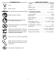
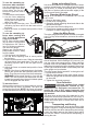
FUNCTIONAL DESCRIPTION 1 2 10 3 9 8 4 7 12 6 14 13 5 15 11 16 24 17 18 19 22 23 6 21 20
1. Rip scale indicator use accessories specifically WARNING Only recommended for this tool. Others 2. Rip scale may be hazardous. If any parts are damaged or missing, do not operate this tool until the parts are replaced. Use of this product with damaged or missing parts could result in serious personal injury. Do not attempt to modify this tool or create accessories not recommended for use with this tool.
Selecting, Installing, and Changing Blades 8. Match the arrow direction on the replacement saw blade with the arrow direction on the riving knife. The teeth should point toward the front of the table saw. Slide the blade onto the spindle. heed this warning could result in personal injury. 9. Install the outer blade flange. The flat side of the Use the appropriate saw blade for WARNING the riving knife. Match kerf width flange must rest against the blade. of blade (>1.8 mm) and blade body thickness (<1.
Changing the Riving Knife Installing Anti-kickback Pawls the appropriate saw blade for WARNING Use the riving knife. Match kerf width install the anti-kickback WARNING Always pawls onto the riving knife with of blade (>1.8 mm) and blade body thickness (<1.55 mm) with the marking on the riving knife to reduce the risk of kickback. Failure to heed this warning could result in personal injury. Two riving knives are provided with the saw; the riving knife with guard, and the riving knife without guard.
To use the extending rip fence as a table extension: Use the extending rip fence to hold the edge of the workpiece when the fence is moved out past the end of the table. 1. Pull the fence lock forward. 2. Use the fence adjusting knob to move the extending rip fence out past the edge of the table. 3. Flip the fence extension over. The tab on the extending rip fence will fit into the lower slot on the fence. 4. Adjust the fence as needed and push the fence lock back.
ONE-KEY™ Avoiding Kickback To learn more about the ONE-KEY™ functionality for •Always use the correct blade depth setting. The this tool, please refer to the quick reference included with top of the blade teeth should clear the workpiece this product or go to milwaukeetool.com/One-Key. To by 1/8" to 1/4". download the ONE-KEY™ app, visit the App Store or Google Play from your smart device. 1/8" - 1/4" ONE-KEY™ Indicator Solid Blue Wireless mode is active and ready to be configured via the ONE-KEY™ app.
not allow familiarity with tools WARNING Do to make you careless. Remember sure the screws in a push block CAUTION Be are recessed to avoid damaging the that a careless fraction of a second is sufficient to inflict severe injury. Do not use any attachments or accessories not recommended by the manufacturer of this tool. The use of attachments or accessories not recommended can result in serious personal injury. saw or workpiece.
How to Mount a Featherboard Bevel Cross Cut - Cuts made with an angled blade. Bevel cross cuts are across the wood grain, and bevel rip cuts are with the grain. not locate the featherboard to WARNING Do the rear of the workpiece. If posi- tioned improperly, kickback can result from the featherboard pinching the workpiece and binding the blade in the saw kerf. Failure to heed this warning can result in serious personal injury. Completely lower the saw blade.
Making a Cross Cut Making a Miter Cut sure the blade guard assemWARNING Make bly is installed and working prop- sure the blade guard assemWARNING Make bly is installed and working prop- erly to avoid serious possible injury. Using the rip fence as a cutoff gauge when cross cutting will result in kickback which can cause serious personal injury. 1. Remove the battery pack. 2. Remove the rip fence. 3. Set the blade to the correct depth for the workpiece. 4.
Making a Bevel Rip Cut Making a Large Panel Cut Make sure the saw is properly secured to a work surface to avoid tipping from the weight of a large panel. sure the blade guard assemWARNING Make bly is installed and working properly to avoid serious possible injury. Never make freehand cuts (cuts without the miter gauge or rip fence). Unguided workpieces can result in serious injury. 1. Remove the battery pack. 2. Set the blade to the correct depth for the workpiece. 3.
Troubleshooting 10. Turn ON the saw. Allow the saw to come to full speed. 11. Use a push stick and/or push blocks to move the piece into the cut. 12. Turn OFF the saw. Wait for the blade to come to a complete stop before removing the workpiece. 13. Once all non-through cuts are complete, remove the battery pack and reinstall the riving knife with guard and anti-kickback pawls. Problem Excess vibration. Making a Dado Cut WARNING Blades are sharp. Wear work gloves when handling blades.
Saw Battery overshuts off temperature unexpectedly Allow battery to cool for 10 minutes before use. Throat Plate Set Screws MAINTENANCE reduce the risk of injury, always WARNING To unplug the charger and remove the battery pack from the charger or tool before performing any maintenance. Never disassemble the tool, battery pack or charger. Contact a MILWAUKEE service facility for ALL repairs. Maintaining Tool 2.
To check for 45°: 8. Set the blade angle to 45° and lock into place. 9. Place a combination square beside the blade on the right using the 45° side. The edge of the 45° side of the square and the saw blade should be parallel. NOTE: Make sure that the square contacts the flat part of the saw blade, not the blade teeth. 10. If the blade and square are not parallel: • Unlock the bevel locking lever. • Loosen the 45° adjustment screw.
5. Place a speed square or straight edge against riving knife over the saw blade. The saw blade and riving knife are aligned when the speed square contacts the riving knife on BOTH sides, without making contact with the blade. There should be a very thin gap between the square and the blade. The square should not contact the blade teeth. 7. Blade should contact fence evenly, front to back. 8. If not, use a 4 mm hex wrench to loosen the appropriate fence post (front and/or back).
8. Recheck both sides of the blade/riving knife. SERVICE - UNITED STATES 9. Repeat until riving knife is properly adjusted to (1.800.729.3878) the blade. Monday-Friday, 7:00 AM - 6:30 PM CST 10. Once adjusted, remove the riving knife, reinstall or visit www.milwaukeetool.com the throat plate, then reinstall the riving knife and anti-kickback pawls (if appropriate for the Contact Corporate After Sales Service Technical operation). Support with technical, service/repair, or warranty ONE-KEY™ questions.
LIABLE FOR ANY INCIDENTAL, SPECIAL, CONSEQUENTIAL OR PUNITIVE DAMAGES, OR FOR ANY COSTS, ATTORNEY FEES, EXPENSES, LOSSES OR DELAYS ALLEGED TO BE AS A CONSEQUENCE OF ANY DAMAGE TO, FAILURE OF, OR DEFECT IN ANY PRODUCT INCLUDING, BUT NOT LIMITED TO, ANY CLAIMS FOR LOSS OF PROFITS. SOME STATES DO NOT ALLOW THE EXCLUSION OR LIMITATION OF INCIDENTAL OR CONSEQUENTIAL DAMAGES, SO THE ABOVE LIMITATION OR EXCLUSION MAY NOT APPLY TO YOU.
SÉCURITÉ INDIVIDUELLE et s'assurer qu'aucun autre problème risque d'affecter le bon fonctionnement de l'outil. En cas de dommages, faire réparer l’outil avant de l’utiliser. Plusieurs accidents sont causés par des produits mal entretenus. •Garder les outils bien affûtés et propres. Des outils correctement entretenus et dont les tranchants sont bien affûtés risquent moins de se bloquer et sont plus faciles à contrôler. •Utiliser l’outil électrique, les accessoires, les embouts etc.
pure transversale avec le guide d’onglet. Diriger la pièce de travail avec la butée de longueur et le guide d’onglet au même temps augmentera la probabilité de rebond et blocage dans la lame de la scie. •Lors des opérations de sciage, toujours appliquer de la force pour passer la pièce de travail entre la butée et la lame de la scie.
Avertissements à propos des méthodes d’opération de la scie à table Le plus souvent durant le rebond, la pièce de travail s’élève sur la table par l’arrière de la lame et est projetée vers l’opérateur. Le rebond est causé par une mauvaise utilisation de la scie et/ou des méthodes de travail incorrectes et il peut être évité en prenant les précautions suivantes : •Ne jamais se tenir en ligne avec la lame. Veuillez se tenir bien campé dans le même sens du guide par rapport à la lame.
•Maintenir en l’état les étiquettes et les plaques d’identification.Des informations importantes y figurent. Si elles sont illisibles ou manquantes, contacter un centre de services et d’entretien MILWAUKEE pour un remplacement gratuit.
DESCRIPTION FONCTIONNELLE 1 2 10 3 9 8 4 7 12 6 14 13 5 15 11 16 24 17 18 19 22 23 26 21 20
MONTAGE DE L'OUTIL Ne recharger la batterie AVERTISSEMENT qu’avec le chargeur spéci- 1. Indicateur d’échelle longitudinale 2. Échelle longitudinale fié. Pour les instructions de charge spécifiques, lire le manuel d’utilisation fourni avec le chargeur et les batteries. 3. Loquets de guide 4. Loquet de plaque à gorge Insertion/Retrait de la batterie Pour retirer la batterie, enfoncer les boutons de déverrouillage et la tirer hors de l’outil.
Montage de la scie à table dans le couteau diviseur. Ne pas utiliser de lames de coupe de métaux. Ne pas couper de plastique. La clé de lame doit être remise dans le cadre de la scie à table (voir la section de « Description fonctionnelle » pour en savoir plus à propos de l’emplacement de rangement). REMARQUE : Pour la substitution de la lame avec une lame spéciale, suivre les instructions fournies avec l'accessoire. Pour remplacer la lame de la scie : 1. Retirer le bloc-piles. 2.
1. Retirer le bloc-piles. 2. Soulever la lame en tournant le volant de réglage de la hauteur à droite. 3. Relâcher le levier de blocage du couteau diviseur. 4. Pour le retirer, tirer du couteau diviseur en le soulevant. 5. Pour l’installer, insérer le couteau diviseur dans la fente directement à l’arrière de la lame jusqu’à ce qu’il soit bien mis en place. REMARQUE : Si le levier de blocage n'est pas totalement ouvert, il est possible que le couteau diviseur ne soit pas bien mis en place. 6.
Pour utiliser le Guide de refente extensible lorsque vous coupez des pièces minces (19 mm (3/4") ou moins) à proximité de la lame: REMARQUE : N'utilisez que le Guide de refente extensible dans cette position pour les pièces 19 mm (3/4") épais ou moins. Pour les pièces plus épaisses, utiliser la jauge d'onglet. Toujours utiliser un bâton poussoir pour tenir les mains à une distance minimale de 76 mm (3") par rapport à la lame. 1. Tirer le verrou de guide longitudinal vers le front. 2.
ONE-KEY™ 4. Pousser le levier de verrouillage de biseau vers le bas. 5. Vérifier le dégagement de guide avant de faire la coupe. Faire une coupe pilote avant de commencer à travailler Pour en apprendre plus long sur la fonctionnalité ONE-KEY™ de cet outil, veuillez consulterà la référence rapide fourni incluse avec ceproduit ou visitez le milwaukeetool.com/One-Key.
•Pièce à couper non soutenue Démarrage/arrêt de la scie •Coupe forcée et verrouiller soiAVERTISSEMENT Vérifier •Coupe de planches humides ou voilées gneusement tous les ré•Utilisation d'une lame inadéquate pour le type de glages et faire tourner la lame d’un tour complet coupe pour s’assurer qu’elle tourne librement avant •Procédures de travail incorrectes d’insérer le bloc-piles.
APPLICATIONS Refente Poignée Cet outil peut être utilisé pour les applications cidessous : •Coupes en ligne droite telles que les coupes transversales, en long, d'onglets, en biseau et composées •Le rainage et le moulurage, avec des lames en option •Ébénisterie et menuiserie REMARQUE : Cette scie à table est conçue pour couper du bois et des produits dérivés du bois uniquement. Ne pas couper de métal. Ne pas couper de plastique. Arrêt Conseils de coupe To use a jig: 1.
Comment monter une cale-guide Coupes d'onglet : Des coupes effectuées avec la planche sur toute position autre que 90°. La lame est verticale. Les planches ont tendance à glisser pendant la coupe d'onglet. Cela peut être contrôlé en maintenant la pièce fermement contre le guide d'onglet. pas placer la cale-guide AVERTISSEMENT Ne à l'arrière de la pièce.
Réalisation d’une coupe longitudinale de minimiser le risque AVERTISSEMENT Afin de blessure à cause du d'éviter le risque de AVERTISSEMENT Afin blessures graves, rebond, vérifier l’alignement correct après la rémission, la chute, le heurtement ou l’usage excessif de l’outil. Un outil mal aligné pourra causer du blocage et entraîner des blessures physiques graves. Voir la section « Entretien » pour en savoir plus à propos de la méthode de réglage approprié.
5. Insérer le bloc-piles. 6. Avant de démarrer la scie, s'assurer que le bois ne touche pas la lame. 7. DÉMARRER la scie. Laisser la scie parvenir à sa vitesse maximale. 8. Maintenir la pièce fermement avec les deux mains sur le guide d'onglet et engager la pièce sur la lame. REMARQUE : La main la plus proche de la lame doit être placée sur la poignée de verrouillage du guide d'onglet et la main la plus éloignée, sur la pièce à couper. 9. ARRÊTER la scie.
Réalisation d’une coupe de pièces de grande taille 3. Installer le couteau diviseur. 4. Régler l’angle de biseau à 0º. 5. Régler la lame sur la profondeur de coupe correcte pour la pièce. 6. Selon la forme et la taille de la pièce, utiliser le guide longitudinal ou le guide d'onglet. 7. Installer une cale-guide à la position adéquate pour la coupe à réaliser. 8. Insérer le bloc-piles. 9. Avant de démarrer la scie, s'assurer que le bois ne touche pas la lame. 10. DÉMARRER la scie.
10. Utiliser un bâton poussoir ou des blocs poussoir pour déplacer la pièce à couper. 11. ARRÊTER la scie. Attendre que la lame s'arrête complètement avant de retirer la pièce. 12. Une fois toutes les coupes non traversantes terminées, retirer le bloc-piles et réinstaller la lame standard, la plaque à gorge, le couteau diviseur avec carter ainsi que les griffes anti-rebond. La scie ne démarre pas La lame ne coupe pas correctement. Dépannage Problème Vibrations excessives.
6. Si la lame et l’équerre ne sont pas parallèles : • Désengager le levier de verrouillage de biseau. • Desserrer la vis de réglage à 0º. 3. Réglage de lame à fente d’onglet 4. Réglage de lame à guide longitudinal 5. Réglage de couteau diviseur à lame de scie Vis de réglage à 0º de minimiser le risque AVERTISSEMENT Afin de blessure, toujours re- tirer le bloc-piles avant d’effectuer tout entretien ou réglages. Came à 0º Vis pointeau 1.
3. Réglage de lame à fente d’onglet (talon) 6. Glisser le guide au-dessus jusqu’à ce qu’il touche la lame et engager le levier de verrouillage de guide longitudinal. 1. Retirer le bloc-piles. 2. Régler l’angle de la lame (biseau) à 0º et le verrouiller sur place. 3. Soulever la lame en tournant le volant de réglage de la hauteur à droite. 4. Mesurer dès l’avant de la lame jusqu’à la fente d’onglet et dès l’arrière de la lame à la fente d’onglet. Il faut que toutes les deux mesures soient égales. 5.
5. Réglage de couteau diviseur à lame de scie Pour vérifier l'alignement du couteau diviseur : 1. Retirer le bloc-piles. 2. Soulever la lame en tournant le volant de réglage de la hauteur à droite. 3. Retirer les griffes anti-rebond du couteau diviseur avec carter de lame. 4. Enlevez le couteau diviseur et placez-le à plat sur la table. Le couteau diviseur doit être plat et ne pas incliner lorsqu'un bord est touché.
Nettoyage aucune preuve d’achat n’est fournie lorsqu’une demande de service sous garantie est déposée. L’ACCEPTATION DES RECOURS EXCLUSIFS DE RÉPARATION ET DE REMPLACEMENT DÉCRITS DANS LES PRÉSENTES EST UNE CONDITION DU CONTRAT D’ACHAT DE TOUT PRODUIT MILWAUKEE. SI VOUS N’ACCEPTEZ PAS CETTE CONDITION, VOUS NE DEVEZ PAS ACHETER LE PRODUIT.
ADVERTENCIAS DE SEGURIDAD GENERALES PARA LA HERRAMIENTA ELÉCTRICA Lea todas las advertencias de ADVERTENCIA seguridad, instrucciones, ilus- use protección para los ojos. El equipo de protección, tal como una máscara contra polvo, calzado antideslizante, casco o protección auditiva, utilizado para condiciones adecuadas disminuirá las lesiones personales. •Evite el arranque accidental.
•Mantenga las herramientas de corte afiladas y •Siempre use una guarda de hoja de sierra, cuchillo limpias. Las herramientas de corte correctamente divisor y dispositivo para evitar contragolpes mantenidas con bordes de corte afilados son menos para cada operación de desbrozado. Para las propensas a atorarse y son más fáciles de controlar.
a 50 mm. Los dispositivos de “ayuda en el trabajo” mantendrán su mano a una distancia segura de la hoja de la sierra. •Use solo la barra de empuje provista por el fabricante o construida de conformidad con las instrucciones. Esta barra de empuje provee suficiente distancia de la mano desde la hoja de la sierra. •Nunca use una barra de empuje dañada o cortada. Una barra de empuje dañada puede romperse, causando que su mano se resbale hacia la hoja de la sierra. •No realice ninguna operación “a manos libres”.
1. Indicador de la escala de corte al hilo •Limpie con frecuencia y retire el aserrín debajo de la mesa de la sierra, o del dispositivo de recolección de polvo. El aserrín acumulado es combustible y puede encenderse por sí solo. •La sierra de mesa debe estar fija. Una sierra de mesa que no esté fija correctamente puede moverse o voltearse. •Retire las herramientas, desperdicios de madera, etc. de la mesa antes de encender la sierra de mesa. Una distracción o posible atasque puede ser peligroso.
DESCRIPCION FUNCIONAL 1 2 10 3 9 8 4 7 12 6 14 13 5 15 11 16 24 17 18 19 22 23 47 21 20
ENSAMBLAJE la batería sólo con ADVERTENCIA Recargue el cargador especificado SIMBOLOGÍA Volts para ella. Para instrucciones específicas sobre cómo cargar, lea el manual del operador suministrado con su cargador y la batería. Corriente continua Como se inserta/quita la batería en la herramienta Revoluciones por minuto sin carga (RPM) C Para retirar la batería, presione los botones de liberación y jale de la batería para sacarla de la herramienta.
Montaje de la sierra de mesa NOTA: Para reemplazar la hoja con una hoja accesoria, siga las instrucciones provistas con el accesorio. Para cambiar la hoja de la sierra: 1. Extraiga la batería. 2. Fije el ángulo de la hoja (bisel) a 0° y asegúrela en su lugar. 3. Levante la hoja girando la altura, ajustando el volante de mano hacia la derecha. 4. Retire el cuchillo divisor. 5. Retire la placa de garganta. 6. Oprima el seguro del husillo y gire el husillo/hoja hasta que se bloquee. 7.
12. Revise que la protección de la hoja y los trinquet- 6. Cierre la palanca de liberación del cuchillo es que evitan contragolpes se muevan libremente completamente. antes de encender la sierra. Asegúrese de que los 7. Tire suavemente del cuchillo divisor para asegurar dientes de la hoja vayan en la misma dirección que esté fijo en su lugar. que la rotación indicada en el cuchillo divisor. 8.
1. Tire del seguro de la guía hacia adelante. Cambio de la profundidad de la hoja La profundidad de la hoja debe estar fija para que las 2. Use la manija para ajustar la guía para mover la posición de la guía de corte. puntas exteriores de la hoja estén por encima de la pieza de trabajo por aproximadamente 3 mm (1/8") a 3. Voltee la extensión de la guía. Deslice la guía de corte de extensión hacia atrás y luego empuje 6 mm (1/4"), pero los puntos más bajos (gargantas) hacia abajo.
Calibre de inglete NOTA: una descarga eléctrica alta de la herramienta puede causar que la aplicación de ONE-KEY™ pierda la conexión. Siga las indicaciones de la aplicación para volver a conectarse. Cuerpo del calibre de inglete OPERACION Con el fin de minimizar el ADVERTENCIA riesgo de lesiones, siempre utilice la protección de ojos adecuada indicada para cumplir con lo dispuesto en la norma ANSI Z87.1.Use protección auditiva.
4. Para encender la sierra en ON, levante la cubierta del interruptor y luego levante el interruptor. 5. Para apagar la sierra en OFF, oprima la cubierta del interruptor hacia abajo. No permita que el conoADVERTENCIA cimiento que tiene de las herramientas lo vuelva descuidado. Recuerde que, una fracción de segundo de descuido es suficiente para provocar una lesión grave. No use ningún accesorio que no recomiende el fabricante de esta herramienta.
Cómo hacer una mesa con canto biselado no se acerquen a 76 mm (3") de distancia de la hoja de la sierra. Use la barra de empuje provista con la sierra de mesa, o pueden hacerse de varios tamaños y formas con madera sobrante, y usarse para un proyecto en específico. La barra debe ser más angosta que la pieza de trabajo, con una muesca de 90° en un extremo y con una forma que ayude al agarre en el otro extremo. Un bloque de empuje tiene una empuñadura sujetada con tornillos empotrados desde el lado inferior.
asegúrese de que el ADVERTENCIA Siempre cuchillo divisor con protec- Reglas del corte Esta sierra de mesa puede realizar una variedad de cortes que no se mencionan todos en este manual. NO intente hacer ningún corte que no esté cubierto aquí, a menos que esté completamente familiarizado con los procedimientos correctos y accesorios necesarios. Su biblioteca local tiene muchos libros sobre uso de sierra de mesa y procedimientos de carpintería especializados para su referencia.
Hacer un corte de inglete 6. NOTA: se recomienda que coloque la pieza que se va a guardar en el lado izquierdo de la hoja para que pueda hacer un corte de prueba primero en la madera sobrante. 7. Encienda la sierra en ON. Permita que la sierra llegue a su máxima velocidad. 8. Sostenga la pieza de trabajo con firmeza con ambas manos en el calibre de inglete y alimente la pieza de trabajo en la hoja.
10. Apague la sierra en OFF. Espere a que la hoja Hacer un corte de inglete (bisel) compuesto se detenga totalmente antes de retirar la pieza de que el ensADVERTENCIA Asegúrese de trabajo. amble de la protección de la hoja esté instalado y funcionando correctamente, Hacer un corte al hilo biselado Asegúrese de que el ens- a fin de evitar una posible lesión grave.
Hacer un corte no desbrozado Hacer un corte de bisel Los cortes no desbrozados pueden hacerse con la textura (corte al hilo) o sobre la textura (corte transversal). El uso de un corte no desbrozado es fundamental para cortar ranuras, machihembrados y cortes de bisel. Este es el único corte del tipo que se hace sin el cuchillo divisor con la protección de la hoja instalada. Use el cuchillo divisor sin la protección de la hoja.
Resolución de problemas Problema Vibración excesiva. Causa BLa hoja está fuera de Reemplace la hoja. equilibrio. La hoja está dañada. Reemplace la hoja. La hoja no está montada fijamente. Apriete todos los accesorios. La superficie de trabajo no es uniforme. Vuelva a posicionar en una superficie plana. Ajuste las patas de la base opcional. La hoja está deforme. La guía de corte no se mueve de manera uniforme. El corte atasca o quema el trabajo La guía de corte no está montada correctamente.
Para reducir el riesgo de lesión, WARNING siempre retire las baterías antes de Tornillo de ajuste a 0° realizar algún servicio o ajustes. Leva a 0° 1. Ajustar la placa de garganta Tornillo puntero use la placa de garganta WARNING Siempre correcta para la operación. Difer- entes hojas pueden requerir diferentes placas de garganta. Nunca opere la sierra sin una placa de garganta en su lugar. Una placa de garganta ajustada es importante para tener un corte uniforme.
3. Ajuste para la hoja a la ranura de inglete (escora) Poste C Tornillo de alimentación Poste A Poste B 1. Extraiga la batería. 2. Fije el ángulo de la hoja (bisel) a 0° y asegúrela en su lugar. 3. Levante la hoja girando la altura, ajustando el volante de mano hacia la derecha. 4. Mida desde la parte frontal de la hoja a la ranura del inglete y la parte trasera de la hoja a la ranura 6. Deslice la guía para que toque la hoja y bloquee del inglete. Deben ser iguales. la palanca de bloqueo de la guía. 5.
19. Repita el paso hasta que la guía toque la hoja de manera uniforme. La guía debe alojarse completamente en el riel de la guía con el colgante por el borde del riel de la guía. 20. Haga dos o tres cortes de prueba en madera sobrante desde cada lugar de la guía. Si los cortes no son adecuados, repita el proceso. Tornillos de ajuste del cuchillo divisor 5. Ajuste del cuchillo divisor a la hoja de la sierra Para revisar la alineación del cuchillo divisor: 1. Extraiga la batería. 2.
Limpieza La fecha de manufactura del producto se utilizará para determinar el periodo de garantía si no se proporciona comprobante de compra al solicitar el servicio en garantía. LA ACEPTACIÓN DE LOS REMEDIOS EXCLUSIVOS DE REPARACIÓN Y REEMPLAZO AQUÍ DESCRITOS ES UNA CONDICIÓN DEL CONTRATO PARA LA COMPRA DE TODO PRODUCTO DE MILWAUKEE. SI USTED NO ACEPTA ESTA CONDICIÓN, NO DEBE COMPRAR EL PRODUCTO.
MILWAUKEE TOOL 13135 West Lisbon Road Brookfield, WI 53005 USA 58140089d3 06/19 08930801601Q-01(A) Printed in Taiwan