
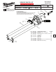
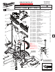
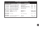
Service Parts List


1
2
3
4
5
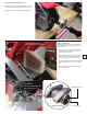
LUBRICATION NOTES:
Type ‘Y’ Grease
No. 49-08-5270, 6oz. tube
When servicing the gears or the Gear Case,
90-95% of the old grease must be removed
prior to new grease being added. Clean gear
assemblies with a clean, dry cloth.
Place a heavy layer of grease to the pinion
teeth of the Rotor Assembly.
Place a heavy layer of grease to the gear
teeth of the 1st gear of the Intermediate
Gear Assembly.
Place a heavy layer of grease to the teeth of
the bevel pinion of the Intermediate
Gear Assembly.
Place a heavy layer of grease to the teeth of
the bevel gear of the Spindle Assembly.
Lightly coat inside axle bores at the rear of the Motor Arm Assembly.
Lightly coat the back end of the Down Lock Pin and the corresponding cavity
in the Bevel Arm Assembly with grease.
Place a thin coat of grease to the surface of the Bevel Axle, being sure to get
grease into the outer grooves. Lightly coat the corresponding cavities in the
Bevel Arm Assembly.
Place a dab of grease to detent ball and spring of the Bevel Handle Assembly.
Coat Washers with a light film of grease. Rounded edges of washers must face
each other.
Brush a light film of grease to the outside surface on the Bevel Arm Assembly
that contacts with the Bevel Hub.
1
2
3
4
5
1
2
3
4
5
1
2
3
4
1
2
3
Place a light coat of grease to the two slotted areas (both sides of the part) on
the Detent Slider.
Place a dab of grease to the two raised catch tabs on the Detent Spring.
Place a light coat of grease to the two slotted areas (both sides of the part) on
the Chop Stop Slider Assembly.
1
2
3
6
7
Place 15 grams ±1 of grease in intermediate gear cavity of Gear Case.
Place 5 grams ±1 of grease in spindle gear cavity of Gear Case.
5
1
2
Brush a heavy coat of grease to the center
surface of Base as shown.
Coat the Thick Washer and the four Bevel
Spring Washers with grease. Orient the parts
as shown in the detail.
1
2
6
7
7