
Use and Care Manual


6
7
the mechanical accuracy of the miter angle detent
plate. It calibrates itself each time the turntable is
placed in a miter detent and it requires no adjustment.
Using the Miter Angle Fine Adjust in conjunction with
the Digital Miter Angle Readout, it is easy to make ac-
curate minor angle adjustments anywhere along the
miter range. Using these systems together makes
it easy to re-position the turntable and repeat any
miter angle setting.
When the turntable is positioned at a LEFT miter angle
the digital readout will display with a (-) symbol in front
of the angle (for example: -22.5° or -44.7°). When
the turntable is positioned at a RIGHT miter angle the
digital readout will display as follows: 22.5° or 44.7°.
Dual Bevel Adjustment System
The Dual Bevel Adjustment System allows for quick
and accurate bevel adjustments to either the Right
or the Left. The bevel angle can be set using de-
tents (stops) for the following commonly cut angles
0°, 22.5°, 33.85°, 45° Right and Left. The bevel
mechanism also has several degrees of overtravel
beyond 45° on both the left and right.
Electronic Feedback Control Circuit
The Electronic Feedback Control Circuit (EFCC)
helps improve the operation and life of the tool. It al-
lows the tool to maintain constant speed and torque
between no-load and load conditions. The soft start
reduces the amount of torque reaction at startup to
the tool and the user. It gradually increases the motor
speed up from zero to the top no-load speed.
Electric Brake
The electric brake engages when the trigger is re-
leased, causing the blade to stop and allowing you
to proceed with your work. WARNING! The brake is
not a substitute for the guards, so it is essential to
always wait for the blade to stop completely before
removing the blade from the kerf. Generally the saw
blade stops in four to fi ve seconds. However, there
may be a delay between the time the trigger is re-
leased and the time the brake engages. Occasionally
the brake may miss completely. If the brake misses
frequently, the saw needs servicing by an authorized
MILWAUKEE service station.
Lights
The Milwaukee 6950-20 Miter Saw has two high
power lights positioned on either side of the blade
to illuminate the workpiece cutting area so that it is
easy to see blade approach the cutting line. An ON
/ OFF switch for the lights is conveniently located on
the trigger handle. The bulb is designed to provide
several years of service. Uses standard bulb size
GE 193.
Dust Management System
The Milwaukee 6955-20 Miter Saw dust collection
system uses a large dust chute on both sides of the
blade to capture and direct dust to back of the saw.
The saw comes with a Dust Elbow and a Dust Bag
that attach to the back of the Dust Chute. The dust
bag has a zipper located on the bottom of the bag
that makes it easy to empty. When using the saw on
a stand, the dust bag zipper can be left open to allow
the waste to fall into a waste container.
Carrying Handles
For ease of transporting, multiple carrying handles
are provided, one on each side of the table and one
on top of the saw head. Always lock the saw head
down when transporting.
ASSEMBLY
WARNING
To reduce the risk of injury, always
unplug tool before attaching or
removing accessories or making adjustments.
Use only specifi cally recommended accessories.
Others may be hazardous.
Adjusting the Miter Saw
The 6955-20 Miter Saw is fully adjusted at the factory.
If it is not accurate due to shipping and handling,
please follow these steps to accurately set up your
saw. Once the saw is properly adjusted, it should
remain accurate under normal jobsite and transporta-
tion conditions.
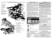
Squaring the Blade (90°) to the Fence (0° Miter)
1. Unplug saw
2. Place a square against the fence and blade and
ensure that the square is not touching blade teeth
as this will cause an inaccurate measurement.
3. Loosen the miter lock knob and move the saw to
the 0° miter position. Do not tighten the lock knob.
4. If the saw blade is not exactly perpendicular to the
fence, use the supplied wrench to loosen the screws
that hold the miter scale to the base. Move the
scale left or right until the blade is perpendicular to
the fence. Use the square to verify that the blade is
perpendicular to the fence. Retighten the screws.
5. Loosen the miter pointer adjustment screw and
reposition the pointer the so that it indicates ex-
actly zero. Once the pointer is properly positioned,
retighten the miter pointer adjustment screw.
Squaring the Blade (90°) to the Table (0° Bevel)
1. Unplug saw
2. Place a square against the table and blade and
ensure that the square is not touching blade teeth
as this will cause an inaccurate measurement.
3. Remove the 6 screws holding the dust chute
together.
4. Move the bevel adjustment lever to the middle
position and wedge in a tool (screw driver etc.)
so the handle stay in the middle position. Move
the saw head so that the bevel detent mechanism
locks into the 0° bevel detent.
5. Loosen 2 screws (T25) on the front of the bevel arm,
these screws are used to clamp the detent body.
6. Using a T25 wrench you can adjust the bevel set-
ting of the blade-to-table. Clockwise tilts blade to
the right, counterclockwise tilts blade to the left.
7. When you have the blade set to the 0° bevel,
torque the 2 screws to 85-100 in lbs.
8. Remove the tool used to wedge the bevel adjust-
ment lever.
9. Move the bevel adjustment lever to "lock".
10. Reassemble the dust chute sides, tightening the
6 screws securely.
11. If necessary, loosen the left and right bevel pointer
adjustment screws and reposition the pointers
the so that they indicates exactly zero. Once the
pointers are properly positioned, retighten the
bevel pointer adjustment screw.
Mounting the Miter Saw
To prevent the tool from sliding, falling or tipping
during operation, the saw can be mounted to a sup-
porting surface such as a level, sturdy work table
or bench. Position the saw and workbench to allow
adequate room for cross-cutting long workpieces. To
mount the saw, insert fasteners through the holes in
the corners of the saw base.
Installing the Dust Bag
Use the dust bag to collect or divert sawdust. Insert
the dust elbow into the dust chute on the back of the
saw. Then, attach the dust bag by hooking it onto the
dust elbow. Always empty the dust bag before storing
and frequently during use.
Raising and Lowering the Saw Head
The saw head must be locked down for transporting
and storing the tool. The tool is shipped with the saw
head locked down. To unlock it, press and hold down
the saw head and simultaneously pull out the lock
down pin. To lock the saw head, press and hold down
the saw head and then push in the lock down pin.
Locking and Unlocking the Sliding Mechanism
Always lock the sliding mechanism before trans-
porting or storing the saw. To unlock it, loosen the
slide rail lock by turning it counterclockwise. To lock
it, tighten the slide rail lock by turning it clockwise.
Lock-Off
There is a hole in the trigger through which a padlock
will fi t to lock the tool when it is not in use. Use a pad-
lock with a 1/4" shackle and always unplug the tool
before installing it (padlock not supplied with tool).
Selecting the Correct Miter Saw Blade
Use only sliding miter saw blades with the
MILWAUKEE Sliding Dual Bevel Miter Saw. Saw
blades with a 0° hook angle or a negative hook angle
work well for Sliding Miter saws. A negative hook
angle means that teeth tip away from the direction
of rotation, and a 0° degree hook angle means that
the teeth are in line with the center of the blade. A
low or negative hook angle will slow the feed rate and
will also minimize the blade’s tendency to “climb” the
material being cut.
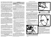
Installing and Changing Blades
Always use clean, sharp blades because dull blades
tend to overload the tool, bind and cause pinching. Use
only 12" blades rated at least 5500 RPM.
1. Unplug the tool.
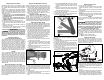
2. With the saw head up, use the wrench to loosen
the guard bracket rear screw 1/4 turn using the
wrench provided (1).
3. Raise the lower guard (2).
Loosen guard
bracket rear
screw
Rotate lower
guard up
1
2
4. Loosen (do not remove) the guard bracket front
screw (3) until the guard bracket can be raised to
expose the blade screw (4). Lower the lower guard
until it rests on the guard bracket front screw. This
will hold it up and out of the way during the blade
change.
Loosen guard
bracket
front screw
3
4
Rotate guard
bracket up
5. Press in the spindle lock and rotate the spindle
until the lock engages.
6. Use the wrench to loosen and remove the left-hand
thread blade screw clockwise.
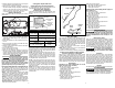
7. Remove the outer blade flange, blade, blade
washer, and inner blade fl ange. Wipe the fl anges,
washer, and spindle to remove dust and debris.
Inspect the parts for damage. Replace if needed.
Outer fl ange
Inner fl ange
Blade
Blade
screw
Blade
washer
8. Install the inner blade fl ange as shown.
9. Insert the blade washer into the blade arbor hole.
10. Match the arrow on the blade with the arrow on
the lower guard. Slide the blade into the upper
guard and onto the spindle.
11. Install the outer blade fl ange.
12. Press in the spindle lock and rotate the blade until
the lock engages. Insert and securely tighten the
blade screw counterclockwise with the wrench.
13. Rotate the guard bracket into position and se-
curely tighten the two screws. Return the wrench
to the wrench holder.
14. Lower the saw head and check the clearance
between the blade and the adjustable kerf plates.
Important: The lower guard must move freely. The
blade should rotate freely (see "Adjusting the Kerf
Plates").