
Use and Care Manual

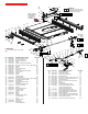
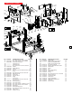
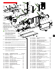
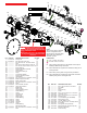
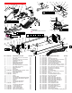
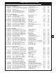

FIG. PART NO. DESCRIPTION OF PART NO REQ.
17 43-97-0010 Riving Knife (1)
95 06-83-0011 M5 x 8mm Set Screw, S2.5 (3)
100 --------------- M4 x 8mm Pan Hd. T-20 Sems Screw (1)
101 --------------- Stem (1)
102 --------------- M5 x 16mm Cap Hd. Mach. Screw, S4 (2)
103 --------------- M4 x 22.5mm Cap Hd. Mach. Screw, S4 (2)
104 --------------- Bowed Retainer (1)
105 --------------- Riving Knife Attachment Plate (1)
106 --------------- Spring Sleeve (1)
107 --------------- M4 Hex Nut with Nylon (2)
108 --------------- Spring (1)
109 --------------- Anyi-Rotating Washer (1)
110 --------------- Riving Knife Clamp Handle (1)
111 --------------- Handle Shaft (1)
112 06-82-0076 M5 x 13mm Pan Hd. T-25 Mach. Screw (2)
113 44-66-0043 Blade Change Outer Plate (1)
114 44-66-0044 Blade Locking Plate (1)
115 06-82-0078 M5 x 20mm Pan Hd. T-25 Mach. Screw (3)
116 40-50-0146 Spring (1)
117 06-55-0007 5/8-18 UNF RH Hex Nut (1)
118 43-34-0011 Outer Flange Washer (1)
119 --------------- Blade Shaft (1)
121 --------------- Retaining Ring (1)
122 --------------- Gearcase Bearing Plate (1)
123 --------------- Sealed Bearing (1)
124 --------------- O-Ring (1)
125 --------------- Gearcase Cap (1)
126 --------------- Helical Gear (1)
127 --------------- Retaining Ring (3)
128 --------------- Sealed Bearing (1)
129 34-40-0101 O-Ring (1)
130 34-40-0103 O-Ring (1)
131 28-14-0006 Gearcase (1)
132 34-40-0104 O-Ring (1)
133 --------------- Sealed Bearing (1)
134 --------------- Motor Bearing Plate (1)
135 06-82-0081 M5 x 15mm Pan Hd. T-25 Mach. Screw (6)
136 --------------- Rotor (1)
5
111
110
109
108
107
(2x)
17
105
106
104
95
(3x)
103
(2x)
101
100
102
(2x)
115
(3x)
114
112
(2x)
113
116
117
118
119
121
122
123
124
125
126
127
128
129
130
132
127
(2x)
133
135
(2x)
134
136
137
(3x)
138
139
131
145
144
(3x)
135
(4x)
141
142
(6x)
143
140
146
150
147
148 149
137 138 139
140 141
276
127 133 134
135 136
277
119 121 122 123 124
125 126 127 128 129
274
95 100 101 102 103 104 105
106 107 108 109 110 111
273
= Type ‘Y’ Grease, 49-08-5270
LUBRICATION:
®
= 277 Red Loctite, 44-22-0325
112 Apply a drop of Red Loctite 277 to the threads of screws prior to
installing on Blade Change Outer Plate.
126 Place a liberal amount of grease to the Helical Gear being sure to
coat all gear teeth.
131 Place a heavy coat of grease in the gear cavity of Gearcase.
136 Apply a liberal amount of grease to the Pinion Gear of the Rotor
Assembly, being sure to cover all gear teeth.
NOTE:
When servicing gears or gearcase,
90-95% of old grease must be
removed prior to new grease being
added. Clean gear assemblies
with clean, dry cloth.
GEARCASE and MOTOR ASSEMBLY
FIG. PART NO. DESCRIPTION OF PART NO REQ.
137 --------------- M4.5 x 22mm Pan Hd. T-20 Screw (3)
138 --------------- FanBae (1)
139 --------------- Stator (1)
140 --------------- Motor Housing (1)
141 --------------- PCBA (1)
142 06-82-0083 M3.5 x 14mm Pan Hd. ST T-10 Screw (6)
143 31-50-0011 Top Motor Cover (1)
144 06-82-0087 M4.5 x 14mm Pan Hd. ST T-20 Screw (3)
145 42-52-0018 Motor End Cap (1)
146 50-11-0020 Coin Cell Battery (CR-2032N/BN) (1)
147 31-50-0012 Bottom Motor Cover (1)
148 31-21-0011 One-Key Battery Cover (1)
149 06-82-0089 M2.6 x 6mm Pan Hd. ST Phillips Screw (1)
150 42-26-0011 8.25" Blade (1)
273 42-68-0014 Riving Knife Clamp Assembly (1)
274 14-30-0031 Blade Shaft with Gearcase Cap Assy. (1)
276 --------------- Electronics Assembly (1)
277 16-07-0010 Rotor Assembly (1)
DO NOT attempt to service or replace the
electronics package #276. Electronics Ser-
vicing can only be performed at this Milwaukee
factory Central Repair Center:
MILWAUKEE ELECTRIC TOOL Central Repair
1013 Sycamore Avenue
l
Greenwood, MS
38930-7277