
Use and Care Manual


4
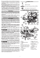
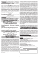
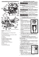
Installing the Anti-Splinter Device
The anti-splinter device helps
Shoe
Anti-splinter
device
stabilize the workpiece and re-
duce workpiece splinter.
NOTE: Do not use the transpar-
ent blade cover and anti-splinter
device when making bevel/
angle cuts.
1. Remove the battery pack.
2. Slide the anti-splinter device
onto the shoe. Make sure the
anti-splinter device is installed ush with the bot-
tom of the shoe.
Installing the Shoe Cover
The shoe cover is used to prevent marring and
scratching of the workpiece surface. To attach the
shoe cover:
1. Remove the battery pack.
2. Hook the front of the cover over the steel shoe.
3. Snap the rear of the shoe cover over the back of
the shoe. Be sure both sides are snapped in place.
4. When the shoe cover is not needed, remove it by
pulling the tabs on rear of the shoe cover down.
Unhook the front of the shoe cover and remove.
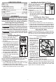
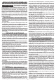
Adjusting the Shoe
The shoe may be tilted up to 45° in either direction.
NOTE: Do not use the transparent blade cover and
anti-splinter device when making bevel/angle cuts.
To set a tilt angle for bevel/angle cuts:
(Cat. No. 2737-20)
1. Remove the battery pack.
2. Loosen the shoe
adjustment lever.
3. Pull the base for-
ward slightly until
the detents are not
engaged.
4. Tilt the shoe to
the required pre-
set angle (0°, 15°,
30°, or 45°) and
push the shoe into
the detent.
5. To set an angle
other than the pre-
sets, set the de-
sired angle without
engaging a detent.
6. Tighten the shoe adjustment lever.
7. Make a test cut to verify the angle.
NOTE: If the shoe begins to slip when the lever is
tightened, use the 4 mm hex wrench stored in the
shoe to tighten the shoe adjustment hex sockets.
Remove the shoe cover, turn the tool over, and
tighten the hex sockets securely.
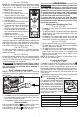
SPECIFICATIONS
Volts.............................................................. 18 DC
Battery Type .................................................M18™
Charger Type................................................M18™
Recommended Ambient
Operating Temperature ......................0°F to 125°F
Cat. No. ..................................................... 2737-20
No Load Strokes per Minute ...................... 0 - 3500
Length of Stroke .................................................. 1"
Cat. No. ...................................................2737B-20
No Load Strokes per Minute .................. 800 - 3500
Length of Stroke .................................................. 1"
ASSEMBLY
WARNING
Recharge only with the charger
specied for the battery. For spe-
cic charging instructions, read the operator’s
manual supplied with your charger and battery.
Removing/Inserting the Battery
To remove the battery, push in the release buttons
and pull the battery pack away from the tool.
WARNING
Always remove battery pack before
changing or removing accessories.
To insert the battery, slide the pack into the body
of the tool. Make sure it latches securely into place.
WARNING
Only use accessories specically
recommended for this tool. Others
may be hazardous.
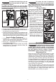
Installing Saw Blades
Use only T-Shank jig saw blades.
Slot Blade
1. Remove the battery pack.
2. Push and hold the Quik-Lok
tension lever to right to line up
the slots.
3. Fit the saw blade into the groove
in the support roller and push it
rmly into the plunger as far as it
will go; the lug of the saw blade
must be in the plunger.
4. Release the Quik-Lok tension
lever to secure the saw blade.
5. Check that the saw blade is held
rmly; the slot in the plunger will
be at an angle to the blade.
6. To remove the blade, push the
lever to the right and the blade
will be ejected.
Installing the Transparent Blade Cover
Do not use the transparent blade cover and anti-
splinter device when making bevel/angle cuts.
1. Remove the battery pack.
2. To install, place the transparent blade cover in
front of the blade and slide it into place. The tabs
will snap into the slots on the housing.
3. To remove, press in the sides of the transparent
blade cover and pull away from the blade.