
Use and Care Manual


4
ASSEMBLY
WARNING
Recharge only with the charger
specied for the battery. For spe-
cic charging instructions, read the operator’s
manual supplied with your charger and battery.
Removing/Inserting the Battery
To remove the battery, push in the release buttons and
pull the battery pack away from the tool.
WARNING
Always remove battery pack before
changing or removing accessories.
To insert the battery, slide the pack into the body of the
tool. Make sure it latches securely into place.
WARNING
To reduce the risk of injury, always
use a side handle when using this
tool. Hold securely.
Installing Side Handle
The side handle may be installed on either side of
the gear case. Position the side handle in the loca-
tion which offers best control and guard protection.
To install, thread side handle into handle socket and
tighten securely.
Installing the Bail Handle
1. Remove battery pack.
2. Remove side handle.
3. Position the bail handle in the position (left or right
orientation) that offers best control.
4. Slide the handle around the front of the tool and up
onto the body of the tool.
5. Fit the handle into both handle sockets.
6. Select one of the three angle positions that offers
best control - forward, 90°, or back.
7. Insert the hex cap screws into each side of the bail
handle and tighten securely with the hex wrench
provided.
Installing/Removing/Cleaning
the Dust Screen
Using the dust screen will increase the performance
and extend the life of the tool.
CAUTION Do not use tool without dust screen in-
stalled.
1. To attach the dust screen, snap the screen over the
tool’s handle.
2. To remove the dust screen, insert a at screwdriver
into the notch at the top of the dust screen and pry
away from the tool.
3. To clean the dust screen, tap against a hard surface,
or blow clean with compressed air.
Using the Trigger Lock
The trigger can be locked off for storage and transport,
unlocked for use, or locked on for continuous use.
1. To LOCK OFF the trigger, press the trigger lock from
the locked side of the tool.
2. To UNLOCK the trigger, press the trigger lock from
the unlocked side of the tool.
3. To LOCK ON the trigger for continuous use, pull
the trigger and press in the trigger lock from the
unlocked side of the tool. Release the trigger.
To stop the tool, pull and release the trigger again.
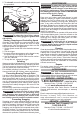
Installing Polishing Pads/ Bonnets
1. To install, remove the battery pack and place the
tool on its tool rest with the spindle upright.
2. Press and hold the spindle lock button.
3. Thread the backing pad onto the spindle. Hand-
tighten securely.
4. Press the polishing pad/bonnet securely onto the
backing pad. Use a centering tool, if provided, to
ensure the pad is aligned for proper balance.
•
WARNING
Some dust created by power sanding,
sawing, grinding, drilling, and other
construction activities contains chemicals known to
cause cancer, birth defects or other reproductive harm.
Some examples of these chemicals are:
• lead from lead-based paint
• crystalline silica from bricks and cement and other
masonry products, and
• arsenic and chromium from chemically-treated lumber.
Your risk from these exposures varies, depending on
how often you do this type of work. To reduce your
exposure to these chemicals: work in a well ventilated
area, and work with approved safety equipment, such
as those dust masks that are specially designed to
lter out microscopic particles.
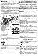
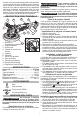
FUNCTIONAL DESCRIPTION
3
8
9
5
10
11
1. Spindle lock button
2. Side handle
3. Tool rest
4. Speed control dial
5. Handle
6. Trigger
7. Trigger lock
8. Dust guard
9. Backing pad
10. Polishing pad
11. Bail handle
4
1
2
6
7
SYMBOLOGY
Volts
Direct Current
Rated Revolutions per Minute (RPM)
C
US
UL Listing Mark for Canada and the U.S
SPECIFICATIONS
Cat. No. ..................................................... 2738-20
Volts .............................................................. 18 DC
Battery Type .................................................M18™
Charger Type ................................................M18™
Rated RPM ................................................ 0 - 2200
Pad Diameter....................................................... 7"
Spindle Thread Size .................................... 5/8"-11