
Use and Care Manual


5
SYMBOLOGY
Volts
Direct Current
Rated Revolutions per Minute (RPM)
C
US
UL Listing Mark for Canada and the U.S.
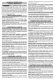
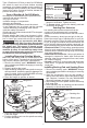
FUNCTIONAL DESCRIPTION
1. Spindle lock
2. Handle
3. Dust screen
4. Switch lock-off (2780-20)
5. Paddle switch (2780-20)
Slide switch (2781-20)
6. Side handle
Cat. No. 2780-20
1
6
5
4
7
3
7. Guard
8. Accessory
9. Guard lock lever
2
Cat. No.
2781-20
5
2
9
8
ASSEMBLY
WARNING
Recharge only with the charger
specied for the battery. For spe-
cic charging instructions, read the operator’s
manual supplied with your charger and battery.
Removing/Inserting the Battery
To remove the battery, push in the release buttons
and pull the battery pack away from the tool.
WARNING
Always remove battery pack before
changing or removing accessories.
To insert the battery, slide the pack into the body
of the tool. Make sure it latches securely into place.
WARNING
To reduce the risk of injury when
grinding, always use properly in-
stalled guards.
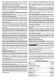
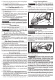
Removing/Installing/Adjusting the Guard
This tool is shipped with a guard. Always use a guard
unless otherwise indicated by these instructions.
1. To remove the guard, remove the battery pack
and remove any accessories from spindle.
2. Press in the guard lock lever and rotate the guard
to line up the tabs on the grinder with the slots in
the guard.
3. Press in the lock lever and lift the guard straight
up and away from the tool.
4. To install the guard, remove the battery pack and
remove any accessories from the spindle.
NOTE: Use only 4-1/2" grinding wheels with 4-1/2"
guards (available as an accessory). Use only 5"
grinding wheels with 5" guards.
5. Line up the tabs on the grinder with the slots in
the guard.
6. Press in the guard lock lever and press the guard
onto the tool.
7. To adjust the guard, press in the guard lock lever
and rotate the guard to one of ve detent slots.
WARNING! Always adjust the guard to provide the
operator with maximum protection while operating.
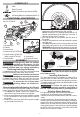
Operator's Zones
WARNING
To reduce the risk of injury, always
use a side handle when using this
tool. Hold securely.
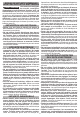
Installing Side Handle
The side handle may be installed on either side of
the gear case. Position the side handle in the loca-
tion which offers best control and guard protection.
To install, thread side handle into side handle socket
and tighten securely.
WARNING
To reduce the risk of injury, the
operator should be instructed in
the use, care and protection of grinding wheels.
Grinding Wheel Selection
Use grinding wheels, and accessories that are:
• correct size as written on tool’s nameplate.
• rated at or above the RPM listed on the tool’s name-
plate.
• correct accessory, wheel type and grit for the job.
Grinding is the cutting action of thousands of abrasive
grains on the face of a grinding wheel. When grinding
metals such as steel and iron, choose an aluminum
oxide grinding wheel. Select a silicon carbide grinding
wheel for stone and concrete. Use cotton reinforced
wheels for non-ferrous metals.