
Operator's Manual S/N J77A


5
OPERATION
WARNING
To reduce the risk of injury, always
wear proper eye protection marked
to comply with ANSI Z87.1.
When working in dusty situations, wear appro-
priate respiratory protection or use an OSHA
compliant dust extraction solution.
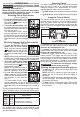
Selecting Drill or Drive Action
(Cat. No. 2803-20)
1. To use the drilling mode, rotate
the torque selector collar until the
drill symbol appears in line
with the arrow.
2. To use the driving mode rotate
the torque selector collar until the
desired clutch setting appears in
line with the arrow.
The adjustable clutch, when
properly adjusted, will slip at a
preset torque to prevent driving
the screw too deep into dierent
materials and to prevent damage to the screw or
tool.
Selecting Hammer, Drill or Drive Action
(Cat. No. 2804-20 )
1. To use the hammer-drilling
mode, rotate the torque selector
collar until the hammer symbol
appears in line with the ar-
row. Apply pressure to the bit to
engage the hammering mecha-
nism.
NOTE: When using carbide bits, do not use water
to settle dust. Do not attempt to drill through steel
reinforcing rods. This will damage the carbide bits.
2. To use the drilling only mode,
rotate the torque selector collar
until the drill symbol appears
in line with the arrow.
NOTE: The number selected on
the torque selector collar has no
eect on operation of the drill in drilling mode.
3. To use the driving screws
mode rotate the torque selector
collar until the desired clutch set-
ting appears in line with the
arrow.
The adjustable clutch, when
properly adjusted, will slip at a preset torque to
prevent driving the screw too deep into dierent
materials and to prevent damage to the screw or
tool.
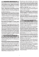
The torque specications shown here are approximate
values obtained with a fully charged battery pack.
TORQUE SPECIFICATIONS
Clutch
Setting
in. lbs Applications
1-4
5-8
9-11
12-14
25-40
45-60
65-75
80-90
Small screws in softwood.
Medium screws in softwood
or small screws in hardwood.
NOTE: Because the settings shown in the table are
only a guide, use a piece of scrap material to test
the dierent clutch settings before driving screws
into the workpiece.
Selecting Speed
The speed selector is on top of the motor housing.
Allow the tool to come to a complete stop before
changing speeds. See “Applications” for recom-
mended speeds under various conditions.
1. For Low speed, push the speed selector to display
“1”.
2. For High speed, push the speed selector to display
“2”.
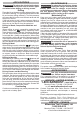
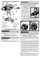
Using the Control Switch
The control switch may be set to three positions:
forward, reverse and lock. Due to a lockout mecha-
nism, the control switch can only be adjusted when
the ON/OFF switch is not pressed. Always allow the
motor to come to a complete stop before using the
control switch.
LOCK
Push to CENTER
Reverse
Forward
For forward (clockwise) rotation, push in the control
switch from the right side of the tool. Check the
direction of rotation before use.
For reverse (counterclockwise) rotation, push in the
control switch from the left side of the tool. Check
direction of rotation before use.
To lock the trigger, push the control switch to the
center position. The trigger will not work while the
control switch is in the center locked position. Always
lock the trigger or remove the battery pack before
performing maintenance, changing accessories,
storing the tool and any time the tool is not in use.
WARNING
To reduce the risk of injury, always
hold or brace securely.
Starting, Stopping and Controlling Speed
1. To start the tool, grasp the handle(s) rmly and
pull the trigger.
NOTE: An LED is turned on when the trigger is
pulled and will go o shortly after the trigger is
released.
2. To vary the speed, increase or decrease the pres-
sure on the trigger. The further the trigger is pulled,
the greater the speed.
3. To stop the tool, release the trigger. Ensure the
tool has come to a complete stop before laying
the tool down.