
Operator’s Manual


5
ONE-KEY™
To learn more about the ONE-KEY™ functionality for
this tool, please refer to the quick reference included with
this product or go to milwaukeetool.com/One-Key. To
download the ONE-KEY™ app, visit the App Store or
Google Play from your smart device.
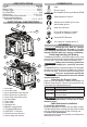
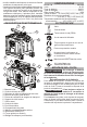
ONE-KEY™ Indicator
Solid Blue Wireless mode is active and ready
to be congured via the ONE-KEY™
app.
Blinking Blue Tool is actively communicating with
the ONE-KEY™ app.
Blinking Red Tool is in security lockout and can
be unlocked by the owner via the
ONE-KEY™ app.
OPERATION
WARNING
Always remove battery pack before
changing or removing accesso-
ries. Only use accessories specically recom-
mended for this tool. Others may be hazardous.
To reduce the risk of short circuit, when setting
tool or battery down, do not allow battery to
contact corrosive or conductive uid.
To reduce the risk of injury, wear safety goggles
or glasses with side shields. Always wear leather
gloves over latex/rubber gloves to avoid en-
tanglement. Cable tip may be sharp.
Using the Forward/O/Reverse Switch
The forward/o/reverse switch controls the rotation
of the cable.
1. For forward (clockwise) rotation, turn the forward/
o/reverse switch to the arrow pointing away from
the end of the lever arm
. Check the direction
of rotation before use.
2. For reverse (counterclockwise) rotation, turn the
forward/o/reverse switch to the arrow pointing
towards the front of the lever arm
. Check the
direction of rotation before use.
3. To lock the switch, turn the forward/o/reverse
switch to the center position O. The cable will not
spin while the forward/o/reverse switch is in the
center locked position. Always lock the switch or
remove the battery pack before performing mainte-
nance, transporting the tool, changing accessories,
storing the tool and any time the tool is not in use.
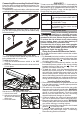
Inserting Cable Into Drain
1. Place the tool at a distance no greater than two feet
from the drain opening. If needed, place protective
covers in the work area.
2. Pull cable out of its carrier and into the rear guide
hose connection using the guide tube. WARNING!
Always wear leather gloves over latex/rubber
gloves to avoid entanglement. Route the cable
directly into the drain from the tool, minimizing
exposed cable and changes in direction.
3. Continue feeding the cable until approximately
one foot of cable remains before the guide tube.
4. Disconnect the cable from its carrier. WARNING!
Rotating cable while still connected to their carriers
may cause striking or crushing injuries.
5. Turn the forward/o/reverse switch to the forward
position
to rotate the cable.
6. If needed, attach additional sectional cables ac-
cording to the instructions under "Connecting/
Disconnecting Sectional Cables".
Connecting/Disconnecting Sectional Cables
Keep the cable couplings clean and lubricated. The
pin key must move freely and fully extend to secure
the connection.
To connect the sectional cables, slide the two cable
couplings together. Make sure the connection is secure.
1 2
To disconnect the sectional cables, insert the pin
key into the coupling hole and pull the cables away
from each other.
1 2
Locking/Unlocking the Lever Arm
The lever arm should be locked any time the tool is
being transported or is not in use.
To lock the lever arm:
1. Turn the forward/o/reverse switch to the OFF
position
2. Lower the lever arm and secure the lever arm hook
(1) into place.
1
Setting Cable Size
Set the tool to the appropriate cable size.
1. Unlock lever latch.
2. Adjust lever arm to line
up arrow with desired
cable size.
3. Lock lever latch.