
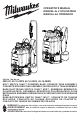
Operator's Manual S/N K62A

4
SPECIFICATIONS
Cat. No. ..................................................... 2820-20
Volts.............................................................. 18 DC
Battery Type .................................................M18™
Charger Type................................................M18™
Tank Capacity ..................................... 4 Gal. (15 L)
Flow Rate ................................... 0.10 to 1.13 GPM
Full Weight .....................................................55 lbs
Recommended Ambient
Operating Temperature ....................32°F to 125°F
Tank Only (Pesticide)........................... 49-16-28PS
Tank Only (Concrete)........................... 49-16-28CS
Tank Only (Water) ............................... 49-16-28WS
ASSEMBLY
WARNING
Recharge only with the charger
specied for the battery. For spe-
cic charging instructions, read the operator’s
manual supplied with your charger and battery.
Removing/Inserting the Battery
To remove the battery, push in the release buttons
and pull the battery pack away from the tool.
WARNING
Always remove battery pack before
changing or removing accessories.
To insert the battery, slide the pack into the body
of the tool. Make sure it latches securely into place.
WARNING
Only use accessories specically
recommended for this tool. Others
may be hazardous.
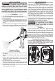
Connecting the Spray Wand
to the Trigger Handle
(Cat. No. 49-16-28PS, 49-16-28CS)
1. Insert the spray wand into the trigger
2
1
handle (1) until rmly seated.
2. Slide the nut onto the threaded cou-
pling and hand tighten securely (2).
3. Pull on the spray wand to be certain
it is properly secured.
4. Place the assembled trigger handle
and wand into one of the wand storage
locations.
Connecting the Nozzles
(Cat. No. 49-16-28PS, 49-16-28CS)
Select and screw on nozzle by job type. When using
the adjustable nozzle, adjust spray pattern as desired
by tightening/loosening the nozzle.
Connecting Water Supply or Nozzle
(Cat. No. 49-16-28WS)
To attach water supply hose to the tool or
1
2
nozzle, push the quick connect tting and
tool/nozzle together (1). Pull on the con-
nection to be certain it is properly secured.
To remove, pull the collar back to release
(2). When using the nozzle, adjust spray
pattern as desired by tightening/loosen-
ing the nozzle.
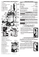
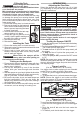
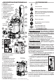
FUNCTIONAL DESCRIPTION
Cat. No.
49-16-28WS
11. Tank hook receptacle
12. Waist strap
13. Adjustable nozzle ^
14. Nozzle holder
15. Battery compartment
16. Battery compartment latch
17. Tank latch
18. Flow rate dial
19. On/O switch
20. On/O light
21. Water nozzle *
22. Adjustable nozzle ^
23. Fan nozzle ^
24. Strainer
25. Tank hooks
26. Gallon markings
27. Liter markings
28. Measuring cup ¤
1. Tank
2. Tank cap
3. Wand storage location
4. Carry handle
5. Spray wand
6. Trigger lock-on ^
7. Trigger handle ^
8. Trigger lock-o ^
9. Shoulder straps
10. Hose
Cat. No.
49-16-28PS
49-16-28CS
* 49-16-28WS only
^ 49-16-28PS and 49-16-28CS only ¤ 49-16-28PS only
2
4
1
5
10
11
15
16
26
27
25
12
13
14
9
3
8
19
20
18
17
21
22
23
24
28
3
6
7