
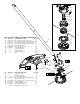
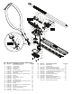
Replacement Parts List
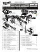


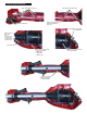

SERVICE WIRING DIAGRAM
Wire Traps and Channels
Wire Traps and Channels
Make sure red wire is
placed completely in
wire trap.
Tighten screw with
HV wire to Drive
Shaft Assembly
Switch Assembly
Motor Insulator/ Encasing
Rotor and Stator
Red wire is connected
to top terminal.
Place wires in this order
from top to bottom:
1. Blue wire
2. Red Wire
3. White wire
Place wires in
this order
from
top to bottom:
1. Blue wire
2. White wire
3. Black wire
Red wire