
User Guide


4
5. With one hand, hold the blade in place between
the rollers and the guides and use the other hand
to position the blade around the pulleys. Be sure
that the blade lies freely within the guard channel
before starting the tool motor.
6. Turn the tension lock handle 180° clockwise to lock
the position. This will secure the blade on the pulleys.
BE SURE THAT THE BLADE IS PROPERLY
SEATED ON THE PULLEYS BEFORE START-
ING THE CUT.
Adjusting the 3-Position Material Guide
1. Remove the battery pack.
2. Press in the guide adjustment button and slide the
material guide to the desired position detent.
OPERATION
WARNING
To reduce the risk of injury, always
wear proper eye protection marked
to comply with ANSI Z87.1.
When working in dusty situations, wear appro-
priate respiratory protection or use an OSHA
compliant dust extraction solution.
Always remove battery pack before changing
or removing accessories. Only use accessories
specically recommended for this tool. Others
may be hazardous.
Keep hands away from the blade and all mov-
ing parts.
Trigger Lock
To lock the trigger, push the trigger lock to the right.
The trigger will not work while the switch is in the
locked position. Always lock the trigger and remove
the battery pack before performing maintenance and
when changing accessories. Lock the trigger when
storing the tool and when the tool is not in use.
Starting and Stopping
This band saw requires both triggers to be pulled
at all times during use. If either trigger is released,
the tool will stop. Release both triggers and restart
the tool.
1. To start the tool, grasp both handles rmly.
2. Pull and hold the rear handle trigger, then, pull the
front handle trigger.
NOTE: The LED is turned on when the rear handle
trigger is pulled. The triggering sequence will reset
after 10 seconds and must be restarted.
3. To vary the speed, increase or decrease pressure
on the rear handle trigger. The further the trigger
is pulled, the greater the speed.
ASSEMBLY
WARNING
Recharge only with the charger
specied for the battery. For spe-
cic charging instructions, read the operator’s
manual supplied with your charger and battery.
Removing/Inserting the Battery
To remove the battery, push in the release buttons
and pull the battery pack away from the tool.
WARNING
Always remove battery pack before
changing or removing accessories.
To insert the battery, slide the pack into the body
of the tool. Make sure it latches securely into place.
WARNING
Only use accessories specically
recommended for this tool. Others
may be hazardous.
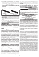
Blades and Blade Selection
The blade dimensions required for this band saw is:
.020" thickness, 1/2" width and 35-3/8" in length. The
special .020" thickness reduces exure fatigue and
provides maximum tooth life. To maximize cutting life,
use a blade with the correct pitch (teeth per inch) for
the specic cutting job.
Blades are available in several pitches. To select the
proper blade, three factors should be considered: The
size, shape, and type of material to be cut.
The following suggestions are for selecting the right
blade for various cutting operations. Keep in mind
that these are broad guidelines and that blade re-
quirements may vary depending upon the specic
size, shape and type of material to be cut. Generally,
soft materials require coarse pitch blades and hard
materials require ne pitch blades. Use coarse pitch
blades for thick work and ne pitch blades for thin
work. It is important to keep at least three teeth in
the cut (see "Typical Application").
• For tough stock 3/8" up to 1" in
diameter or width.
• For tough stock 3/16" up to
1-5/8" in diameter or width.
• For tough stock 5/32" to 3/4" in
diameter or width.
• For thin-wall tubing and thin
sheets heavier than 21 gauge.
• For thin-wall tubing and thin
sheets heavier than 21 gauge.
8 Teeth per Inch
10 Teeth per Inch
14 Teeth per Inch
18 Teeth per Inch
24 Teeth per Inch
WARNING
Do not touch blade immediately
after use. Blade will be hot.
Changing Blades
1. REMOVE BATTERY PACK BEFORE CHANG-
ING OR REMOVING BLADES.
2. Turn the tension lock handle located on the front
of the saw 180° counterclockwise. This releases
the tension on the blade for easy removal.
3. Remove the blades from the pulley rst and then
from the guides.
4. To install a new blade, with the pulleys facing up,
insert the blade between the rollers and the faces
of the guides, making sure that the teeth on the left
side of the tool point towards the rear of the tool.