
Use and Care Manual


4
5
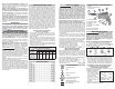
Installing and Removing Bits
TEKS Ramp-Off Locator Assembly
The locator assembly must
Magnetic socket
Locator
Ramp-off
sleeve
be removed when chang-
ing bit sizes.
1. Unplug tool. To remove
the locator assembly,
turn the ramp-off
sleeve while pulling it
away from the tool.
2. Pull out the magnetic
socket and replace it with a new socket.
3. Push the locator assembly onto the nose of the
tool until it snaps into place.
Installing and Removing Bits
Drywall Ramp-Off Locator Assembly
Bit holder
Insert bit
Locator
Ramp-off
sleeve
1. Unplug tool. To remove the locator assembly, turn
the ramp-off sleeve while pulling it away from the
tool.
2. Push insert bit into bit holder until it snaps into
place. Push the bit holder into the nose of the tool
until it snaps into place.
3. Push the locator assembly onto the nose of the
tool until it snaps into place.
Installing and Removing Magnetic
Sockets on Adjustable Screwdrivers
For Cat. No. 6580-20
1. Unplug tool.
2. To remove the magnetic socket, slide the locking
sleeve forward and pull out the socket.
Locking sleeve
Socket
3. To install the magnetic socket, slide the locking
sleeve forward and push in the socket until it is
fully seated.
For Cat. No. 6780-20
1. Unplug tool.
2. To remove the magnetic socket, slide the locking
sleeve forward and pull out the socket.
Locking sleeve
Socket
3. To install the magnetic socket, simply push in the
socket until it snaps into place.
OPERATION
WARNING
To reduce the risk of injury, always
wear safety goggles or glasses
with side shields.
Using Forward/Reverse Switch
1. For forward (clockwise)
Forward
Trigger
Reverse
Switch
Front of Tool
rotation, push the for-
ward/reverse switch to
the left position as
shown.
2. For reverse (coun-
terclockwise) rotation,
push the forward/re-
verse switch to the right
position as shown.
Although an interlock
prevents reversing the
tool while the motor
is running, allow it to
come to a full stop be-
fore reversing.
WARNING
To reduce the risk of injury, keep
hands and cord away from the bit
and all moving parts.
Starting, Stopping and Controlling Speed
1. To start the tool, pull the trigger.
2. To stop the tool, release the trigger.
3. To vary the drilling speed, simply increase or
decrease pressure on the trigger. The further the
trigger is pulled, the greater the speed.
Locking Trigger
The lock button holds the trigger in the ON position
for continuous full speed use.
1. To lock the trigger, hold the lock button in while
pulling the trigger. Release the trigger.
2. To unlock the trigger, pull the trigger and release.
The lock button will pop out.
Adjusting Locator Assembly
The locator assembly controls the tool's driving
depth. These screwdrivers feature a locator assembly
with one-handed depth adjustment. Depth adjust-
ments can be made easily and quickly by turning
the locator with one hand. Detents inside the sleeve
“lock” the selected depth.
For the drywall ramp-off locator assembly, start with
about 1/16" clearance between the head of the screw
and nose with the snap-action clutch disengaged
as shown.
For both locator assemblies, the
1/16"
detents on the inside of the
sleeve represent different
depths. Every two clicks of the
locator equal 1/64". Continue
adjusting the locator to the
desired depth.
1. To increase the driving
depth, simply rotate the loca-
tor in the direction labeled .
2. To decrease the driving
depth, simply rotate the loca-
tor in the direction labeled .
The detents “lock” the locator
in place, ensuring an accurate depth setting.
3. To remove the locator assembly, turn the ramp-off
sleeve while pulling it away from the tool. Reat-
taching the locator assembly will not change the
depth setting.
SPECIFICATIONS
Volts ............................................................. 120 AC
Amps ..................................................................6.5
Cat. No. ..................................................... 6580-20
RPM ............................................................ 0 -1200
Cat. No. ..................................................... 6740-20
RPM ........................................................... 0 - 2500
Cat. No. ..................................................... 6742-20
RPM ........................................................... 0 - 4300
Cat. No. ..................................................... 6780-20
RPM ........................................................... 0 - 2900
Cat. No. ..................................................... 6790-20
RPM ........................................................... 0 - 2500
Cat. No. ..................................................... 6791-20
RPM ........................................................... 0 - 2500
Cat. No. ..................................................... 6791-20
RPM ........................................................... 0 - 2500
Cat. No. ..................................................... 6792-20
RPM ........................................................... 0 - 2500
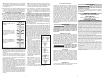
FUNCTIONAL DESCRIPTION
1
2
3
4
7
1. Locator
2. Ramp-off sleeve
3. Nameplate
8
9
10
4. Belt clip
5. Bit clip
6. Handle
7. Lock button
8. Trigger
9. Forward/Reverse switch
10. Gear case
6
5
ASSEMBLY
WARNING
To reduce the risk of injury, always
unplug tool before changing or
removing accessories. Only use accessories
specifi cally recommended for this tool. Others
may be hazardous.
Removing and Replacing Quik-Lok
®
Cords
(Cat. No. 6580-20, 6791-20)
MILWAUKEE's exclusive Quik-Lok
®
Cords provide
instant fi eld replacement or substitution.
1. To remove the Quik-Lok
®
Cord, turn the cord nut
1/4 turn to the left and pull it out.
2. To replace the Quik-Lok
®
Cord, align the connector
keyways and push the connector in as far as it will
go. Turn the cord nut 1/4 turn to the right to lock.
Adjusting Torque Setting
These screwdrivers have a torque setting adjustment
collar for driving different types of screws into different
materials. When properly adjusted, the clutch will slip
at a preset torque to prevent driving the screw too
deep and to prevent damage to the screw or tool.
For Cat. Nos. 6580-20
The 6580-20 Screwdriver has a torque setting adjust-
ment collar that may be adjusted to one of forty-four
settings. The torque is adjustable from 10 to 140
inch-pounds.
To select a setting, turn the adjustment collar in the
direction indicated on the tool. The selected setting
will appear in the window as shown.
HIGHER -TORQUE - LOWER
SETTING
NOTE: Use a piece of scrap material to test the dif-
ferent settings before driving screws into workpiece.
To determine a specifi c setting for your application,
use a torque wrench to check the correct torque at
any particular setting.
For Cat. No. 6780-20
The 6780-20 Screwdriver has a torque setting adjust-
ment collar that may be adjusted to one of twenty-one
settings. The torque is adjustable
from 10 to 140 inch-pounds.
To select a setting, turn the ad-
justment collar on the tool. The
selected setting will appear above
the arrow as shown.
NOTE: Use a piece of scrap mate-
rial to test the different settings be-
fore driving screws into workpiece.
To determine a specifi c setting for your application,
use a torque wrench to check the correct torque at
any particular setting.