
User Guide


5
• lead from lead-based paint
• crystalline silica from bricks and cement and other
masonry products, and
• arsenic and chromium from chemically-treated lumber.
Your risk from these exposures varies, depending on
how often you do this type of work. To reduce your
exposure to these chemicals: work in a well ventilated
area, and work with approved safety equipment, such
as those dust masks that are specially designed to
lter out microscopic particles.
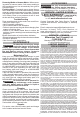
SYMBOLOGY
Volts
Direct Current
Rated Revolutions per Minute (RPM)
Do not use the guard for cut-o
operations
C
US
UL Listing Mark for Canada and the U.S.
SPECIFICATIONS
Cat. No. ...................................... 2880-20, 2881-20
Volts .............................................................. 18 DC
Battery Type .................................................M18™
Charger Type ................................................M18™
Rated RPM .....................................................8 500
Spindle Thread Size .................................... 5/8"-11
Max Capacity ............................................... 5"x1/4"
Recommended Ambient
Operating Temperature .................... 0°F to 125°F
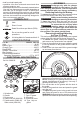
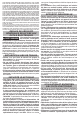
FUNCTIONAL DESCRIPTION
1. Spindle lock
2. Handle
3. Dust screen
4. Switch lock-o (2880-20)
5. Paddle switch (2880-20)
Slide switch (2881-20)
Cat. No. 2880-20
1
6
5
4
7
3
6. Side handle
7. Type 27 guard
8. Accessory
9. Guard lock lever
10. Type 1 clip-on
guard
2
Cat. No.
2881-20
5
2
9
8
10
ASSEMBLY
WARNING
Recharge only with the charger
specied for the battery. For spe-
cic charging instructions, read the operator’s
manual supplied with your charger and battery.
Removing/Inserting the Battery
To remove the battery, push in the release buttons
and pull the battery pack away from the tool.
WARNING
Always remove battery pack before
changing or removing accessories.
To insert the battery, slide the pack into the body
of the tool. Make sure it latches securely into place.
WARNING
To reduce the risk of injury when
grinding, always use properly in-
stalled guards. The guard type must match the
wheel type to provide maximum protection for
the operator if the wheel should break.
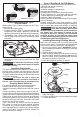
Removing/Installing/Adjusting
the Type 27 Guard
This tool is shipped with a guard. Always use a guard
unless otherwise indicated by these instructions.
1. To remove the guard, remove the battery pack
and remove any accessories from spindle.
2. Press in the guard lock lever and rotate the guard
to line up the tabs on the grinder with the slots in
the guard.
3. Press in the lock lever and lift the guard straight
up and away from the tool.
4. To install the guard, remove the battery pack and
remove any accessories from the spindle.
NOTE: Use only 4-1/2" grinding wheels with 4-1/2"
guards (available as an accessory). Use only 5"
grinding wheels with 5" guards.
5. Line up the tabs on the grinder with the slots in
the guard.
6. Press in the guard lock lever and press the guard
onto the tool.
7. To adjust the guard, press in the guard lock lever
and rotate the guard to one of ve detent slots.
WARNING! Always adjust the guard to provide the
operator with maximum protection while operating.