
Use and Care Manual


4
OPERATION
WARNING
To reduce the risk of injury, always
wear proper eye protection marked
to comply with ANSI Z87.1.
When working in dusty situations, wear appro-
priate respiratory protection or use an OSHA
compliant dust extraction solution.
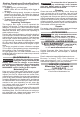
Using the Control Switch
The control switch may be set to three positions:
forward, reverse and lock. Due to a lockout mecha-
nism, the control switch can only be adjusted when
the ON/OFF switch is not pressed. Always allow the
motor to come to a complete stop before using the
control switch.
CENTER TO LOCK
Forward
Reverse
1. For forward (clockwise) rotation, push the control
switch in the direction shown. Check the direction
of rotation before use.
2. For reverse (counterclockwise) rotation, push the
control switch in the direction shown. Check the
direction of rotation before use.
3. To lock the trigger, push the control switch to the
center position. The trigger will not work when the
control switch is in the locked position.
Always remove the battery pack before performing
maintenance or changing accessories. Always
lock the trigger or remove the battery pack before
storing the tool and any time the tool is not in use.
Selecting Speed
Allow the tool to come to a complete stop before
changing speeds. Press the selector button
to
cycle between the settings.
Mode 1 2 3
RPM 0 - 1700 0 - 3000 0 - 3900
Designed for
driving
self-tapping
screws
in sheet metal
IPM 0 - 1400 0 - 3600 0 - 4400
The function is designed to reduce screw strip-
ping, screw breakage, and damage to the work sur-
face when driving self-tapping screws. This function
is optimized for the most common materials, including
#8, #10 and #12 self-tapping screws between 1/2"-1"
in length and 18-22 gauge sheet metal.
NOTE:
mode will only run if the trigger is pulled
more than half-way. If pulled less than half-way, the
driver will run in the normal impacting mode. When
using the
mode, the tool will shut o automatically
once the screw is fully seated.
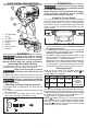
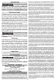
FUNCTIONAL DESCRIPTION
1. 1/4" Hex drive
chuck
2. Tri-LEDs
3. Control switch
4. Trigger
5. Handle
6. Speed control
7. Belt clip
1
2
3
7
6
4
5
ASSEMBLY
WARNING
Recharge only with the charger
specied for the battery. For spe-
cic charging instructions, read the operator’s
manual supplied with your charger and battery.
Removing/Inserting the Battery
To remove the battery, push in the release buttons
and pull the battery pack away from the tool.
WARNING
Always lock the trigger or remove
the battery pack any time the tool
is not in use.
To insert the battery, slide the pack into the body
of the tool. Make sure it latches securely into place.
WARNING
Only use accessories specically
recommended for this tool. Others
may be hazardous.
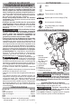
Attaching and Removing Accessories
This impact driver is intended for use with drill and
driver bits.
1. To attach an accessory, press the shank into the
hex drive chuck.
2. To remove the accessory, pull out the ring and
remove the accessory. Release the ring.