
Service Parts List
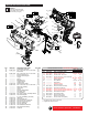
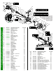
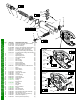

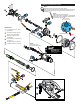

FIG. PART NO. DESCRIPTION OF PART NO. REQ.
4a --------------- Relief Valve Adjuster (1)
4b 34-40-0037 O-Ring (1)
4c 40-50-1006 Relief Valve Spring (1)
4d --------------- Relief Valve Plunger (1)
4e --------------- 2.0mm Ball (1)
5a 06-65-0031 Pin (1)
5b 44-10-0023 Release Lever (1)
5c --------------- Release Valve Pin (1)
5d 34-40-0044 O-Ring (1)
5e --------------- Release Valve Seat (1)
5f --------------- Serrated Seal Washer (1)
5g 45-88-0034 Back Up washer (1)
5h 34-40-0048 O-Ring (1)
5j --------------- Spring Cap (1)
5k --------------- Spring (1)
6a --------------- Hydraulic Cylinder (1)
6b --------------- 4.0mm Seal Plug (1)
6c --------------- Ball Bearing (1)
6d --------------- Dowel Pin (1)
6e --------------- Shear Seal Disc (1)
6f 45-88-0036 Back Up Washer (1)
6g 34-40-0049 O-Ring (1)
6h --------------- Rotary Valve (1)
6j --------------- Thrust Bearing (1)
6k --------------- Thrust Washer (1)
7 --------------- Retaining Ring (1)
8a --------------- Retaining Ring (2)
8b --------------- Lock Ring Washer (2)
8c --------------- Drive Pawl (6)
8d --------------- Sprocket (1)
9 34-40-0058 O-Ring (2)
10 34-40-0028 O-Ring (2)
11 34-40-0038 O-Ring (1)
12a 31-17-0024 Ear Clamp - Cylinder Side (1)
12b 42-14-0023 Bladder (1)
12c 31-17-0034 Ear Clamp - Pump Side (1)
12d --------------- Fill Plug (1)
12e 34-40-0051 O-Ring (1)
12f --------------- Fill Plug Screw (1)
13a --------------- Cam Shaft Retainer (1)
13b --------------- Piston (1)
13c --------------- Pump Sleeve (1)
13d 34-40-0037 O-Ring (1)
13e --------------- Piston Retainer (2)
13f --------------- Intake Seat (1)
13g --------------- 3.0mm Ball (1)
13h --------------- Intake Spring (1)
13j 34-40-0051 O-Ring (2)
13k --------------- Pump Body (1)
13m --------------- High Pressure Check Valve (1)
13n --------------- Ball Bearing (1)
14a --------------- Retaining Ring (1)
14b --------------- Thrust Washer (2)
14c --------------- Roller Bearing Race (1)
GREEN PART NUMBERS ARE COMPONENTS OF KITS AND NOT AVAILABLE AS INDIVIDUAL SERVICE PARTS.
THE GREEN NUMBERS ARE LISTED HERE AS AN AID TO IDENTIFY SIMILAR LOOKING PARTS.
>
>
>
>
>
>
>
14a
4a
4b
4c
4d
4e
6b
6c
7
8a
(2x)
8d
8c
(6x)
8b
6g
6f
6e
6d
6h
6j
6k
5a 5b 5c 5d 5e 5f 5g 5h 4e 5j 5k 6a
12a
12f
12e
12d
12b
12c
13n
10
(2x)
9
(2x)
13m
13k
13a
13e
(2x)
13b
13c
13d
14c
14b
(2x)
14d
14e
14f
24
(2x)
23
(2x)
16
17
19
(2x)
18a
18b
(2x)
20
(3x)
15a
44
13h
13g 13f 13j 11
12a 12b 12c 12d 12e 12f 13a 13b 13c
13d 13e 13f 13g 13h 13j 13k 13m 13n
14a 14b 14c 14d 14e 14f 16
63
12a 12b 12c
12d 12e 12f
62
17 18a 18b
19 20
69
6a 6b
6c
70
4a 4b 4c
4d 4e
71
8a 8b
8c 8d
77
6d 6e 6f 6g
6h 6j 6k
72
4e 5a 5b 5c 5d 5e
5f 5g 5h 5j 5k
74
15a
15
2a 2b 2c 2d 2n 2p 2r 3c 3d
9 10 11 12a 12c 13g 13h 17
79
13k
44
As an aid to installing bladder (12b) onto Pump
Body (13k) and Hydraulic Cylinder (6a),
apply Forcelogic™ Hydraulic Oil to front
and rear lips of the bladder (inside
and outside). NOTE: Ribs on the
inside of lips must be placed
in grooves on Pump
Body and Cylinder.
FIG. PART NO. DESCRIPTION OF PART NO. REQ.
14d --------------- Roller Bearing Cage (1)
14e --------------- Cam Shaft (1)
14f --------------- Ball Bearing (1)
15 --------------- Pressure Sensor (1)
15a --------------- O-Ring (1)
16 44-86-0051 Retaining Ring (1)
17 45-06-0022 Shaft Seal (1)
18a --------------- Gear Case with Gearing (1)
18b 44-60-0056 Motor Mount Pin (2)
19 --------------- Screw (2)
20 05-81-0015 M3 x 6mm Pan Hd. Phillips Screw (3)
23 05-88-0051 M6 x 30mm Socket Hd. Cap Screw (2)
24 05-88-0031 M4 x 30mm Cap Hd. Hex Recess Scr. (2)
44 05-88-0041 M4 x 5mm T-15 Ground Screw (1)
62 14-46-0201 Service Bladder Kit (1)
63 42-54-0171 Pump Body and Camshaft Assembly (1)
69 14-29-0201 Service Gearbox Assembly (1)
70 14-12-0700 Service Cylinder Assembly (1)
71 31-94-0200 Service Relief Valve Assembly (1)
72 31-94-0205 Service Shear Valve Kit (1)
74 31-94-0210 Service Release Valve Kit (1)
77 45-44-0100 Service Sprocket Assembly (1)
79 14-46-0204 Service Maintenance Kit (1)