
Product Manual


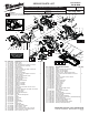


Table Of Contents

49
47
90
57(6x)
13(4x)
56
55
IMPORTANT:
zStrong magnetic force. Care must be taken when installing the Rotor (47) into the Stator Assembly
(49). Do not allow rotor bearing or balancing bushing to hit PCBA on the back end of the stator. This
could cause damage to the PCBA. See figure 1.
zInsert the rotor/stator assembly into pinion bore of the Upper Guard Gearcase Assembly (90).
Carefully wiggle and push the rotor/stator until the ball bearing in front of the fan is fully seated in the
bearing bore of the gearcase. See figure 2.
NOTE: As an aid to installation, apply a light film of lubricant to the bearing bore of the gearcase
before assembling the rotor/stator.
zPlace the Bottom and Top Motor Insulators (55,56) in place around the rotor/stator assembly. Secure
the halves with six Screws (57). A light tapping on the back of the assembled insulator halves may be
necessary to completely seat the insulator halves onto the upper guard gearcase. Fasten the insulator
halves to the gearcase with four Screws (13).
See figure 3. When tightening, alternate the
screws to assure square, even pressure.
Balancing
Bushing
Ball Bearing
Figure 1 Figure 2 Figure 3
PCBA
Switch Lock-Out Button (64)
On-Off Switch (60)
Functionally check Switch Lock-Out (64) by
attempting to turn on tool by applying a rea-
sonable amount of force, up to 8 lbs., to the
switch trigger (60). The tool must not turn on.
Release trigger. Actuate the lock-out lever
and apply a reasonable amount of force to
the switch trigger. The tool must turn on.
While the trigger is still in the "ON" position,
release the lock-out. Release the trigger.
The tool must stop and the lock-out lever
must again prevent the actuation of the
Switch.
Repeat the switch check
two more times.
10
11
Functionally check the Lower Guard (11), with the
saw set at full depth. Place the saw upside down
with the shoe horizontal. Fully retract
the guard and then release it. The
guard must return briskly.
Depth Lever (76) must be
horizontal with shoe (41)
before tightening
76
41
8
Retaining Ring (8) has a side with edges
that are slightly rounded compared to the
other side. When installing on the tool,
position retaining ring with the rounded
edge facing the lower guard.
47
45
Orient Ball Bearing (45) so that
the seal faces the fan of the
Rotor (47) and the open side
faces the gearcase.
11
NOTE:
Do not use grease on
inside diameter of
Lower Guard (11).
Apply a dry Tefl on
®
spray lubricant or
something similar.