
Use and Care Manual


4
5
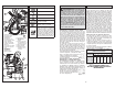
1. Slide rail
2. Carrying handle
3. Feed handle
4. Magnet activation
switch (4272-21 only)
5. Magnet activation knob
(4274-21 only)
6. Speed selector
7. Motor adjustment lever
8. On(I) / Off(O) switch
9. Drill motor
OPERATION
WARNING To reduce the risk of injury,
wear safety goggles or glasses with side
shields.
ASSEMBLY
Attaching Feed Handle
1. To attach, line up the anvil, press the center but-
ton and slide the handle into place on the desired
side of the tool.
2. To remove, press the center button and pull the
handle away from the tool.
Do not use a wrench, pipe, or any other lever in
place of the feed handle.
Motor adjustment lever
The motor adjustment lever is used to raise and
lower the motor on the slide rail. Always hold the
motor securely before loosening the adjustment
lever.
FUNCTIONAL DESCRIPTION
Typical Operation
1. Check the work surface to make sure it is clean
and free of foreign materials.
Paint, rust, scale or uneven surfaces decrease
the holding strength of the magnet. Chips, burrs,
dirt and other foreign materials on the surface
of the magnetic base will also decrease holding
power. Use a smooth, fl at fi le to keep the magnet
clean and free of nicks.
The 4272-21 drill attaches to 3/8" or thicker
ferrous stock, and the 4274-21 to 1/4" or
thicker ferrous stock. Do not use on stock
less than 1/4". The magnetic base WILL NOT
hold on nonmagnetic grades of stainless steel.
2. To install/remove cutter:
A. Unplug tool.
B. Raise the drill motor to its highest position
on the slide rail.
C. Twist the quick-change arbor. Insert the cut-
ter into the arbor and release collar. Tug on
cutter to ensure it is secure. Cutter should
be fully seated into spindle.
D. Reverse procedure to remove cutter.
NOTE: Do not remove cutter unless slug is
removed. Slug may eject unexpectedly. Avoid
contact with cutter tips. Periodically inspect the
cutter tips for loose or damaged tips.
10. Cutting fl uid fi tting
11. Quick-change arbor
12. Safety strap bracket
(strap not shown)
13. Magnetic base
14. LED button
15. Hand pump and
tube (not shown)
1
3
2
4
5
6
7
9
8
1312
14
Fig. B
Fig. C
Fig. A
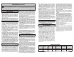
GROUNDING
WARNING Improperly connecting the
grounding wire can result in the risk of elec-
tric shock. Check with a qualifi ed electrician
if you are in doubt as to whether the outlet is
properly grounded. Do not modify the plug
provided with the tool. Never remove the
grounding prong from the plug. Do not use
the tool if the cord or plug is damaged. If
damaged, have it repaired by a MILWAUKEE
service facility before use. If the plug will not
fi t the outlet, have a proper outlet installed by
a qualifi ed electrician.
Grounded Tools: Tools with Three Prong Plugs
Tools marked “Grounding Required” have a three
wire cord and three prong grounding plug. The
plug must be connected to a properly grounded
outlet (See Figure A). If the tool should electrically
malfunction or break down, grounding provides a
low resistance path to carry electricity away from
the user, reducing the risk of electric shock.
The grounding prong in the plug is connected
through the green wire inside the cord to the
grounding system in the tool. The green wire in the
cord must be the only wire connected to the tool's
grounding system and must never be attached to
an electrically “live” terminal.
Your tool must be plugged into
an appropriate outlet, properly
installed and grounded in accord-
ance with all codes and ordinances.
The plug and outlet should look like
those in Figure A.
Double Insulated Tools:
Tools with Two Prong Plugs
Tools marked “Double Insulated” do not require
grounding. They have a special double insula-
tion system which satisfi es OSHA requirements
and complies with the applicable standards of
Underwriters Laboratories, Inc.,
the Canadian Standard Asso-
ciation and the National Elec-
trical Code. Double Insulated
tools may be used in either of
the 120 volt outlets shown in
Figures B and C.
Grounded tools require a three wire extension
cord. Double insulated tools can use either a two
or three wire extension cord. As the distance from
the supply outlet increases, you must use a heavier
gauge extension cord. Using extension cords with
inadequately sized wire causes a serious drop in
voltage, resulting in loss of power and possible tool
damage. Refer to the table shown to determine the
required minimum wire size.
The smaller the gauge number of the wire, the
greater the capacity of the cord. For example, a 14
gauge cord can carry a higher current than a 16
gauge cord. When using more than one extension
cord to make up the total length, be sure each cord
contains at least the minimum wire size required.
If you are using one extension cord for more than
one tool, add the nameplate amperes and use the
sum to determine the required minimum wire size.
Guidelines for Using Extension Cords
• If you are using an extension cord outdoors, be
sure it is marked with the suffi x “W-A” (“W” in
Canada) to indicate that it is acceptable for outdoor
use.
• Be sure your extension cord is properly wired
and in good electrical condition. Always replace a
damaged extension cord or have it repaired by a
qualifi ed person before using it.
• Protect your extension cords from sharp objects,
excessive heat and damp or wet areas.
READ AND SAVE ALL
INSTRUCTIONS FOR FUTURE USE.
* Based on limiting the line voltage drop to fi ve volts at
150% of the rated amperes.
EXTENSION CORDS
Recommended Minimum Wire Gauge
For Extension Cords*
Extension Cord Length
Nameplate
Amperes
25' 50' 75' 100' 150'
0 - 2.0
2.1 - 3.4
3.5 - 5.0
5.1 - 7.0
7.1 - 12.0
12.1 - 16.0
16.1 - 20.0
18
18
18
18
16
14
12
18
18
18
16
14
12
10
18
18
16
14
12
10
--
18
16
14
12
10
--
--
16
14
12
12
--
--
--
WARNING To reduce the risk of injury,
always unplug tool before attaching or remov-
ing accessories or making adjustments. Use
only specifi cally recommended accessories.
Others may be hazardous.
10
11
Cat. No. 4274-21
Cat. No. 4272-21