
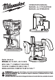
Operator's Manual


7
Feedback Control
The electronic speed control system allows the tool
to maintain constant speed between no-load and
load conditions.
Electronic Overload Protection
These tools are equipped with an electronic overload
protection feature. If the motor shuts o during use,
remove the bit from the workpiece and push the
On/O switch to the OFF (O) position to reset the
tool. Allow the tool to cool before restarting your work.
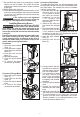
WARNING
Pressing the macro adjustment
button will cause the motor hous-
ing to drop down, which may cause personal
injury or damage to the tool or workpiece. Make
sure your hand is rmly on the motor when press-
ing the button.
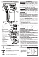
Adjusting the Cutting Depth
Fixed Base
Changes to cutter depth can be read on the depth
scale on the motor housing. Each mark on the scale
indicates a 1/16" change in depth setting. Use the
bottom edge of the removable base as reference
when setting depth of cut. To make deeper cuts,
make successive passes as required, lowering the
bit 1/8" for each pass.
1. Turn the On/O switch to OFF (O) and remove
the battery pack.
2. Open the quick release lever.
3. Press the macro adjustment button and slide the
motor close to the desired depth.
4.
Use the micro adjustment dial to ne-adjust to the
desired depth of cut.
5. Close the quick release lever.
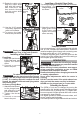
Accessory Plunge Base
The plunge base depth of cut can be set two ways;
for single pass cuts (shallow cuts less than 1/8"), or
for multiple pass cuts.
1/8"
1/4"
3/8"
5/8"
1/2"
Full depth
position
Rod
Micro
adjustment
sleeve
Single Pass Cuts
A shallow cut, such as a mortis cut, can be cut in a
single pass.
1. Turn the On/O switch to OFF (O) and remove
the battery pack.
2. Install the bit and insert the tool into the base.
3. Rotate the depth turret until the highest setting
(5/8") is directly below the depth gauge rod.
4. Loosen the depth gauge knob.
5. Press the plunge release lever and lower the router
motor until the bit touches the workpiece.
6. Release the plunge release lever.
7. Set the depth of cut:
a. Raise the depth gauge rod and slide the piece
to be inlaid (such as a hinge) between the top
turret and the depth gauge rod. Tighten the
depth gauge knob. Remove the reference piece
from the turret.
b. Slide the depth gauge indicator to zero (0) and
then raise the depth gauge rod to the desired
depth of cut. Tighten the depth gauge knob.
NOTE: do not exceed 1/8" cut in a single pass.
8. Make the cut as described in Making the Cut -
Accessory Plunge Base.
Multiple Pass Cuts
For cuts more than 1/8" deep, multiple passes are
necessary.
1. Turn the On/O switch to OFF (O) and remove
the battery pack.
2. Install the bit and insert the tool into the base.
3. Rotate the depth turret until the lowest setting
(full depth position) is directly below the depth
gauge rod.
4. Loosen the depth gauge knob.
5. Press the plunge release lever and lower the router
motor until the bit touches the workpiece.
6. Slide the depth gauge indicator to zero (0).
7. Raise the depth gauge rod to the desired depth
of cut.
8. Tighten the depth gauge knob.
9. Use the micro adjustment sleeve for fine
adjustments (loosen for a shallower cut, tighten
for a deeper cut).
10. Press the plunge release lever and raise the
router motor.
11. Rotate the turret to the highest possible step to
prepare for the rst cut.
12. Make the cut as described in Making the Cut -
Accessory Plunge Base.
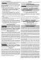
Accessory Oset Base
The depth of cut of the oset bit is set when the bit
is installed.
Holding the Tool
WARNING
Keep hands and body away from
the bit and all moving parts.
Always hold the tool rmly in your hand(s) during
the start-up. The reaction torque of the motor,
as it accelerates to full speed, can cause the
tool to twist.
Maintain a rm grip on the power tool and posi-
tion your body and arm to allow you to resist kick-
back forces. The operator can control kickback
forces, if proper precautions are taken.
Fixed Base and Accessory Oset Base
For best results, hold tool with one hand on the base
and a second hand on the top of the battery pack.