
Service Parts List


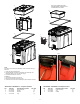


FIG. PART NO. DESCRIPTION OF PART NO. REQ.
1 44-20-8422 Latch Assembly (1)
2 43-44-8422 Gasket
(1)
3 31-01-8423 Dividers (1)
4 31-01-8422 Tray (1)
48-22-8422 PACKOUT™ Compact Toolbox
FIG. PART NO. DESCRIPTION OF PART NO. REQ.
1 44-20-8422 Latch Assembly
(1)
5 31-01-8460 Tray (1)
6 43-44-8460 Gasket
(1)
48-22-8460 PACKOUT™ Compact Cooler
6
5
4
3
2
1
Note: Tray, Dividers and Gasket
illustrated outside of PACKOUT, is to
be assembled on the inside.
1
Note:
Procedure for removal and installation of the 44-20-8422 Latch (1).
Removal:
1. Undo latch from PACKOUT lid.
2. Insert a athead screwdriver in-between latch assembly and
PACKOUT base to pry over the tabs. (Fig.1)
3. Pull metal latch down to remove.
Installation:
1. Insert Latch Assembly into channel.
2. Attach the metal latch to the lid. (Fig.2)
3. Close latch to secure Latch Assembly in place inside the channel.
Fig.1
Fig. 2
11