
Operator's Manual


4
ASSEMBLY
-
WARNING
Recharge only with the charger
changing or removing accessories.
manual supplied with your charger and battery.
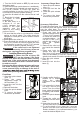
Removing/Inserting the Battery
To remove the battery, push in the release buttons
and pull the battery pack away from the tool.
WARNING
Always remove battery pack before
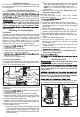
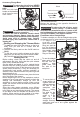
1. To assemble, place collet on an even surface, and
place the nut over the collet.
2. Press down on the nut to snap the nut and collet
together.
3. To disassemble, use a rod to push the collet out
of the nut.
To insert the battery, slide the pack into the body
of the tool. Make sure it latches securely into place.
WARNING
reco
Only use
mmended
accessorie
for thi
s
s tool. Others
may be hazardous.
Always remove battery from tool before changing
or removing accessories. Only use accessories
may be hazardous.
Installing Collets
The collet must be attached to the collet nut before
installing the collet assembly to the tool. Be sure
that the collet size matches the size of the bit shank,
otherwise the collet may break.
Installing/Removing Bits
WARNING
Al
tool
ways
before
remove
attaching
battery
or
from
removing
the
accessories or making adjustments.
Others may be hazardous.
Never use bits larger than the smallest of the
openings in the base, sub-base, or dust shroud.
The use of larger bits can result in loss of control
and possible serious personal injury.
Do not tighten the collet nut without inserting the
bit. The collet may break.
Never touch the bit during or immediately after
use. After use the bit, collet, and collet nut may
be hot enough to burn bare skin.
SYMBOLOGY
Volts
Direct Current
No Load Revolutions per Minute (RPM)
Regulatory Compliance Mark (RCM).
This product meets applicable
regulatory requirements.
Do not dispose of electric tools
together with household waste
material. Electric tools and electronic
equipment that have reached the end
of their life must be collected
separately and returned to an
environmentally compatible recycling
facility.
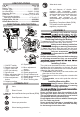
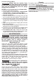
7. Quick release lever
8. Macro adjustment
button
1. ON/OFF switch
2. Speed control dial
3. Collet / collet nut
4. LED (not shown)
5. Spindle lock
6. Micro adjustment dial
17. Shaft / housing hole
9. Gripping surface
10. Depth turret
11. Micro adjustment
sleeve
12. Handles
13. Depth gauge knob
14. Plunge release lever
15. Depth gauge indicator
16. Depth gauge
Cat. No. M18 FTR
5
4
3
2
1
6
Fixed base
7
9
8
17
9
7
FUNCTIONAL DESCRIPTION
Plunge base
14
16
10
11
7
13
15
12
SPECIFICATIONS
Cat. No. ................................................... M18 FTR
Volts............................................................ 18V DC
Battery Type .................................................M18™
Charger Type................................................M18™
No Load RPM ................................ 10,000 - 31,000
Maximum Bit Size ............................. 38mm (1-1/2")
Recommended Ambient
Collet Size ........................... 6.35mm (1/4") & 6mm
Operating Temperature ................... -17°C to 51°C
Plunge Base Cat. No. ........................... 48105601
Offset Base Cat. No. ............................ 48105602
Read Operator's Manual
Wear eye protection.
Wear hearing protection.
Wear dust mask.