
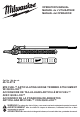
Operator's Manual


5
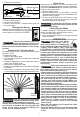
SPECIFICATIONS
Cat. No. ................................................ 49-16-2719
Power Head ............................................... 2825-20
SPM .......................................................... 0 - 3500
Blade Length ..................................................... 20"
Cutting Capacity (diameter) ................................. 1"
Replacement Blades ............... Cat. No.
42-26-2719
SYMBOLOGY
Volts
Direct Current
No Load Strokes per Minute (SPM)
Safety Alert Symbol
Read operator’s manual
Wear eye, hearing, and head protection
Wear non-slip safety footwear
Wear protective gloves
50'
15m
50'
15m
Keep tool at least 50' away from
electric power lines.
50' / 15m
minimum
Keep bystanders at least 50' away
during use.
DANGER
Avoid blade contact
during use
C
US
UL Listing for Canada and U.S.
ASSEMBLY
WARNING
Before use, read manual and labels
of the power head. Important as-
sembly and use instructions are provided in the
power head manual. Connect the attachment to
the power head in accordance with the power
head manual.
Always remove battery pack before changing or
removing accessories.
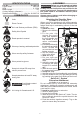
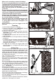
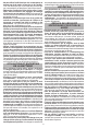
Attaching the Shoulder Strap
(Available as an accessory)
When using this attachment with larger-capacity
battery packs, use the shoulder strap to reduce user
fatigue and help in maintaining control of the tool
during use.
Nut
Bolt
Pole
clip
Bevel
Gate
Carabiner
To install the strap:
1. Remove the battery
pack.
2. Fit the pole clip
around the power
head pole between
the front handle and
rear handle in a lo-
cation comfortable
during use.
3. Insert the bolt through
the pole clip and strap
bevel. Thread the
nut onto the bolt and
tighten securely.
4. Clip the strap cara-
biner to the bevel.
To wear the strap:
1. Put your right arm
and head through the
strap.
2. Adjust the strap clips
to change the strap
length to t comfort-
ably.
3. Slide the neck pad to
the appropriate position.
To unclip the strap:
1. Hold the tool by the front handle with your left hand.
2. Grip the carabiner with your right hand and unclip
by pushing in the gate and it sliding o the bevel.
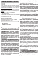
Quik-Lok™ System
Extension Attachment
(Available as an accessory)
Do not extend tool by more than one extension
attachment. Additional extension attachments will
make the pole unstable and dicult to control, which
could result in injury.
To install an attachment or extension:
1. Remove battery pack.
2. Loosen the lock knob.
3. Slide the pole into the Quik-Lok™ latch. The de-
tent on the pole should line up with the slot in the
Quik-Lok™ latch.
4. Push the sections together securely. Tug on the
poles to ensure they are secure.