
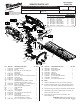
Replacement Part List


LUBRICATION
White Lithium Grease
NOTE:
When servicing the tool, 90-95% of the old grease must be
removed prior to new grease being added.
Apply a heavy coat of grease around the perimeter of the
gear, being sure to cover all gear teeth (approx. 3 grams).
Apply a heavy coat of grease to the motor pinion, being
sure to cover all the pinion teeth (approximately 3 grams).
Apply a thick film of grease to the entire connecting rod,
including the walls of the ID, (2 pieces).
Apply a thick coat of grease to the corresponding contact
area of the crank shaft (approximately 2 grams).
Apply a thick coat of grease to the blade assembly where
there is contact with the connecting rods (approx. 2 grams).
NOTE: DO NOT over lubricate tool! Too much grease can
cause grease discharge through the gear case.
Gear
Pinion
Upper Connecting Rod
Lower Connecting Rod
Blade Assembly
Crank
Shaft
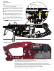
• Attach the Motor Insulator Assembly, containing the Stator (26d), to the Gear Case /Rotor Assembly (45).
Place that assembly rmly and squarely in the Housing Support (33).
• Place the PCBA (26c), Switch (26b) and Battery Connector Block Assembly (26a) rmly and squarely in the
corresponding cavities in the Housing Support (33).
• Route the wires as shown, being sure to push the wires rmly down into the traps (marked with white circles).
• Return Switch Trigger (31), Lock-Off Button (30) and Spring (28) to the proper location in the Housing Support.
• Carefully install the Hand Guard (44) and Housing Cover (32) onto the Housing Support, checking for interferences.
• Secure the Housing Halves and Hand Guard with eight Screws (34) and two Screws (29).
• Check for the the free movement and proper functionality of the Switch and Lock-Off Button.
• Install battery and check for proper operation of the entire tool.
WIRING INSTRUCTION