
Use and Care Manual


4
OPERATION
WARNING
Always remove battery pack before
changing or removing accesso-
ries. Only use accessories specically recom-
mended for this tool. Others may be hazardous.
To reduce the risk of injury, always wear safety
goggles or glasses with side shields.
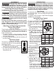
Fuel Gauge
To determine the amount of charge left in the bat-
tery, pull the trigger. The Fuel Gauge will light up for
2-3 seconds.
To signal the end of charge, 1 light on the fuel gauge
will ash for 2-3 seconds.
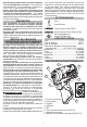
Using the Drive Control
(Cat. No. 2552-20)
The drive control button is used
Speed Indicator
Drive
Control
Button
Auto Shut
O Mode
to adjust the rotation speed
(RPM) for the application.
To select the drive control
mode:
1. Pull and release the trigger
to turn on the tool. The cur-
rent indicator is lit.
2. Press the drive control but-
ton to cycle through the
4 modes. When the desired
mode indicator is lit, begin
work.
* In auto shut o mode ,
Mode RPM IPM
1 0-1300 0-1300
2 0-1900 0-2000
3 0-3200 0-4300
0-3200* -
the tool will drive for-
ward at a reduced RPM
until the torque is
achieved. In reverse the
tool will operate at full
RPM to remove fasten-
ers at full torque.
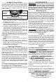
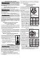
(Cat. No. 2553-20)
The drive control button is
Speed
Indicator
Drive Control Button
Tapping Screw Mode
used to adjust the rota-
tion speed (RPM) for
the application.
To select the drive con-
trol mode:
1. Pull and release the
trigger to turn on the
tool. The current in-
dicator is lit.
2. Press the drive control
Mode RPM IPM
1 0-1300 0-850
2 0-2400 0-2700
3 0-3300 0-4000
0-3300* 0-4000
button to cycle
through the 4 modes.
When the desired mode
indicator is lit, begin
work.
* In self tapping screw
mode, the tool will drive
at full RPM until the
screw taps. Then, for better control, the RPM will
slow as the screw seats to the workpiece.
ASSEMBLY
WARNING
Recharge only with the charger
specied for the battery. For spe-
cic charging instructions, read the operator’s
manual supplied with your charger and battery.
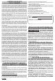
Removing/Inserting the Battery
To remove the battery, push in the release buttons
and pull the battery pack away from the tool.
WARNING
Always remove battery pack before
changing or removing accessories.
To insert the battery, slide the pack into the body
of the tool. Make sure it latches securely into place.
WARNING
Only use accessories specically
recommended for this tool. Others
may be hazardous.
Use only sockets and other accessories speci-
cally designed for use on impact wrenches and
drivers. Other sockets and accessories might
shatter or break causing injury.
Attaching and Removing Accessories
Square Drive Shank
(Cat. No. 2552-20)
These impact wrenchs are intended only for use with
sockets designed for impact wrenches that have a
1/4" square drive. Other sockets could shatter or
break, causing injury.
1. To attach a socket or other accessory, align the
accessory with the drive shank and push it rmly
over the retaining ring.
2. To remove the accessory, pull the accessory o
the drive shank.
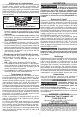
Hex Drive Chuck
(Cat. No. 2553-20)
This driver is intended for use with drill
and driver bits with a 1/4" hex shank and
ball detent recess.
1. To attach an accessory, press the
shank into the hex drive chuck.
2. To remove the accessory, pull out
the ring and remove the accessory.
Release the ring.