
Use and Care Manual

IMPORTANT SAFETY INSTRUCTIONS
WARNING
Read and understand all instructions in this manual and
the manual provided with your power tool. Failure to follow
all instructions listed below, may result in electric shock, re and/or
serious personal injury. Save these instructions.
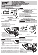
FUNCTIONAL DESCRIPTION
SPECIFICATIONS
Max Capacity .................................. 2" (50 mm)
For use with .................................... 2866-20 M18™ FUEL™ SCREW GUN
ASSEMBLY
WARNING
Only use accessories specically recommended
for this tool. Others may be hazardous.
Attaching to the Screw Gun
1. Remove the battery from the tool.
2. Remove all bits and accessories from the screw gun.
3. Remove the nose cone from the tool.
4. Install the collator bit into the screw gun.
5. Line up the collator with the screw gun and snap into place.
6. To remove, remove battery pack and screws. Press in the tool release but-
tons and pull the collator off of the tool.
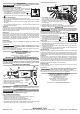
Installing Collated Screw Strips
1. To install, begin
feeding the screw
strip through the screw
strip guide (1).
2. Following the contour of the tool, feed the strip over
the gear wheel, through the nose of the tool (2).
3. The rst screw will "click" into position.
4. NOTE: To remove screws, continue to pull forward over
the gear wheel. Do not pull out from the bottom. This will
damage the gear wheel.
OPERATION
WARNING
To reduce the risk of injury, always wear safety goggles or
glasses with side shields.
Adjusting the Depth of Drive
To adjust the depth of drive, rotate the depth of drive dial.
Continue adjusting the depth locator to the desired depth.
1. To increase the driving depth, turn the dial clockwise .
2. To decrease the driving depth, turn the dial counterclock-
wise
.
Using the Collator
1. Align the nose square against the work surface.
2. Pull the trigger and lock-on the tool according to the screw gun's operator's
manual.
3. Push the tool forward smoothly to sink the screw into the work surface.
4. Lift the tool from the work surface. The next screw in the strip is automati-
cally moved into place.
Maintenance
Keep your tool, battery pack and charger in good repair by adopting a regular
maintenance program. Inspect your tool for issues such as undue noise, mis-
alignment or binding of moving parts, breakage of parts, or any other condition
that may affect the tool operation.
Cleaning
Clean dust and debris from vents. Keep handles clean, dry and free of oil or
grease. Use only mild soap and a damp cloth to clean, since certain cleaning
agents and solvents are harmful to plastics and other insulated parts. Some
of these include gasoline, turpentine, lacquer thinner, paint thinner, chlorinated
cleaning solvents, ammonia and household detergents containing ammonia.
CAT. NO. / NO DE CAT. 49-20-0001
COLLATED DRYWALL ATTACHMENT
ACCESSOIRE EN BANDE POUR PLACOPLÂTRE
ADITAMENTO EN TIRA PARA TABLAROCA
Repairs
For repairs, return the tool, battery pack and charger to the nearest service
center.
Accessories
WARNING
Use only recommended accessories. Others may be haz-
ardous.
For a complete listing of accessories, go online to www.milwaukeetool.com
or contact a distributor.
SERVICE - UNITED STATES
1-800-SAWDUST (1.800.729.3878)
Monday-Friday, 7:00 AM - 6:30 PM CST
or visit www.milwaukeetool.com
Contact Corporate After Sales Service Technical Support with technical,
service/repair, or warranty questions.
Email: metproductsupport@milwaukeetool.com
Become a Heavy Duty Club Member at www.milwaukeetool.com to receive
important notications regarding your tool purchases.
SERVICE - CANADA
Milwaukee Tool (Canada) Ltd
1.800.268.4015
Monday-Friday, 7:00 AM - 4:30 PM CST
or visit www.milwaukeetool.ca
INSTRUCTIONS IMPORTANTES CONCERNANT
LA SÉCURITÉ
AVERTISSEMENT
Lire et comprendre toutes les instructions dans
ce manuel et le manuel fourni avec votre outil
électrique. Le non respect des instructions ci-dessous peut entraîner
un choc électrique, un incendie et des blessures graves. Conserver ces
instructions.
DESCRIPTION FONCTIONNELLE
2
3
1
5
4
6
7
1. Indicateur de longueur de vis
2. Levier de réglage de longueur de vis
3. Cadran de réglage de profondeur
4. Boutons de dégagement de l’outil
5. Guide de vis en bande
6. Échelle de
longueur de vis
7. Buse
SPECIFICATIONS
Capacité max ............................... 50 mm (2")
À utiliser avec ............................... VISSEUSE 2866-20 M18
TM
FUEL™
MONTAGE DE L'OUTIL
AVERTISSEMENT
L’emploi d’accessoires autres que ceux qui sont
expressément recommandés pour cet outil peut
comporter des risques.
Montage à la visseuse
1. Retirer la pile de l’outil.
2. Retirer toutes les mèches et les accessoires de la visseuse.
3. Retirer le cône de buse de l’outil.
4. Installer la mèche de l’assembleuse dans la visseuse
5. Aligner l’assembleuse avec la visseuse et enclencher en place.
6. Pour démonter, retirer le bloc-piles et les vis. Appuyer sur les boutons de
dégagement de l’outil et retirer l’assembleuse de l’outil.
Installer les vis en bande
1. Pour installer,
insérer la vis en
bande dans le guide
de vis en bande (1).
2. En suivant le contour de l’outil, insérer la
bande sur la roue dentée, à travers la buse de l’outil (2).
3. La première vis s’enclenche en place.
4. REMARQUE : Pour retirer les vis, tirer vers l’avant sur la
roue dentée. Ne pas tirer depuis la partie inférieure. Ceci
endommagerait la roue dentée.
1
2
1
2
2
3
1
4
6
7
1. Screw length indicator
2. Screw length adjustment lever
3. Depth adjustment dial
4. Tool release buttons
5. Screw strip guide
6. Screw length scale
7. Nose
5