
Use and Care Manual


6
7
ASSEMBLY
WARNING To reduce the risk of injury,
always unplug tool before attaching
or removing accessories or making adjust-
ments. Use only specifi cally recommended
accessories. Others may be hazardous.
Grinding Wheel Selection
Only use wheels that:
• are high-strength
• are resinoid bond
• are the proper grit
• are the correct size
• are rated at or above the RPM listed on the tool's
nameplate
• have blotters that cover the entire fl ange contact
area.
Grit Selection
The lower the grit number, the coarser the wheel.
Coarser wheels should be used for rough grinding
and fi ner wheels for fi nish grinding (see "Acces-
sories").
Wheel Material
Grinding wheels are made from various materi-
als and are meant for different jobs. Be sure you
choose the proper wheel for the job you plan to
do.
MILWAUKEE Straight Grinders use type 1, straight
wheels as defi ned by the American National Stan-
dards Institute (ANSI). Type 1 straight wheels are
made to be used for edge grinding. They are not
to be used for side grinding.
Care of Grinding Wheels
Grinding wheels should be protected from"
• wetness and extreme humidity
• any type of solvent
• extreme changes in temperature
• dropping and bumping.
Grinding wheels should be stored:
• in an organized way so wheels can be removed
without disturbing or damaging other wheels
• with their safety information.
Grinding wheels should NOT be:
• dropped
• rolled
• bumped.
If any wheel is dropped, rolled, bumped, subjected
to extreme changes in temperature, or has come
into contact with solvents or wetness, discard wheel
immediately.
WARNING To reduce the risk of injury
and damage to the tool, use ONLY accessories
rated at or above the RPM listed on the tool's
nameplate.
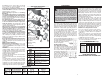
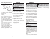
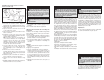
Fig. 1
To Test the Wheel:
NOTE: Wheel must be dry to do this test.
1. Suspend the wheel by its
arbor hole on a small pin
or a fi nger (Fig. 1).
2. Tap the side of the wheel
with the back of a screw-
driver (or any similar,
solid, non-metallic ob-
ject).
3. Rotate wheel 90° and
repeat the test in three
more places.
If the wheel rings, it is in good condition. If it does
not ring, it is bad and should be discarded.
WARNING To reduce the risk of injury,
the wheel guard must be fl ush with the spindle
housing.
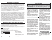
Installing Guard Assemblies
The guards for all tools in this manual are mounted
the same way:
1. Unplug tool and lay it on its tool rest.
2. Loosen guard clamping fasteners.
3. Position guard clamp over the spindle housing
and against the housing shoulder (Fig. 2).
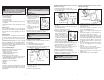
Fig. 2
Spindle
housing
shoulder
Spindle
Guard clamp
4. Position guard so the operator is always behind
the guard. The open edge of the guard should
face the workpiece.
5. Tighten wheel guard clamps.
Installing Grinding Wheels and Accessories
(Cat. No. 5211 only)
1. Unplug tool and lay it on its tool rest.
2. Loosen wing nuts. Move studs aside and swing
the faceplate away.
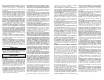
Fig. 3
Inner fl ange
Faceplate
Grinding wheel
Outer fl ange
Spindle
nut
Fig. 4
Inner
fl ange
Outer
fl ange
3. Hold inner fl ange with 1" wrench provided with
the tool.
4. Remove the spindle nut with the 9/16" wrench
provided with the tool.
5. Remove outer fl ange and wheel.
6. Examine both flanges to
ensure that they are free of
nicks and are fl at (Fig. 4).
NOTE: If the fl ange faces
are nicked, or if the inner
surfaces of the fl anges are
not fl at, then replace them
with identical replacement
parts. On Cat. No. 5211, the fl anges should
evenly contact the blotter on the wheel.
7. If you are installing a grinding wheel, inspect and
test it for damage (see "To Test the Wheel").
8. Place the accessory on the spindle.
Never force an accessory onto the spindle. A
forced fi t may damage the accessory.
9. Replace outer fl ange and spindle nut.
10.Tighten spindle nut. Do not overtighten.
11.Swing the faceplate back into place. Move studs
back into slots. Tighten wing nuts.
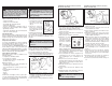
Fig. 5
1. Unplug tool and lay it on its tool rest.
2. Hold inner fl ange with spanner wrench pro-
vided with the tool.
3. Remove the spindle nut with the 1-1/16"
wrench provided with the tool.
4. Remove outer fl ange, rubber washer, and
wheel.
5. Examine both fl anges to ensure that they are
free of nicks and are fl at (see Fig. 4).
NOTE: If the fl ange faces are nicked, or if the
inner surfaces of the fl anges are not fl at, then
replace them with identical replacement parts.
On Cat. No. 5223, the fl anges should evenly
contact the rubber washers on either side of
the wheel.
6. If you are installing a grinding wheel, inspect
and test it for damage (see "To Test the
Wheel").
7. Place the accessory on the spindle.
Never force an accessory onto the spindle. A
forced fi t may damage the accessory.
8. Replace rubber washer, outer flange, and
spindle nut.
9. Tighten spindle nut. Do not overtighten.
Inner fl ange
Rubber
washer
Grinding wheel
Outer fl ange
Spindle nut
WARNING To reduce the risk of injury,
use only identical replacement parts.
Installing Grinding Wheels and Accessories
(Cat. No. 5223 only)