
Use and Care Manual


4
5
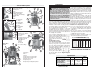
Functional Description
Bodygrip® models
1. Depth adjustment screw
2. Motor release button
3. Locking lever
4. Scale
5. Depth adjustment knob
6. Variable speed dial
7. On/Off switch
8. Cord
9. Motor
10. Handle
11. Collet assembly
12. Sub-base
13. Base
14. Turret
15. Depth stop rod release button
16. Depth stop rod locking screw
17. Plunge release lever
18. Depth stop rod
19. Depth stop rod adjustable pointer
2
3
1
16
17
9
9
18
1. Depth adjustment screw
2. Motor release button
3. Locking lever
4. Scale
5. Depth adjustment knob
6. Variable speed dial
(For Cat. No. 5616-20 only)
7. On/Off switch
8. Motor
9. Cord
6
5
4
7
8
9
10
11
12
13
14
15
10. Body grip
11. Strap
12. Ball handle
13. Collet assembly
14. Sub-Base
15. Base
16. Lock button
17. Trigger
18. D-handle
11
7
12
4
5
8
9
10
13
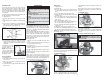
Production
model
1
2
3
6
6
15
16
14
17
18
19
7
9
10
11
12
13
4
5
Plunge base
models
Grounded tools require a three wire extension
cord. Double insulated tools can use either a two
or three wire extension cord. As the distance from
the supply outlet increases, you must use a heavier
gauge extension cord. Using extension cords with
inadequately sized wire causes a serious drop in
voltage, resulting in loss of power and possible tool
damage. Refer to the table shown to determine the
required minimum wire size.
The smaller the gauge number of the wire, the
greater the capacity of the cord. For example, a 14
gauge cord can carry a higher current than a 16
gauge cord. When using more than one extension
cord to make up the total length, be sure each cord
contains at least the minimum wire size required. If
you are using one extension cord for more than one
tool, add the nameplate amperes and use the sum
to determine the required minimum wire size.
Guidelines for Using Extension Cords
• If you are using an extension cord outdoors,
be sure it is marked with the suffi x “W-A” (“W”
in Canada) to indicate that it is acceptable for
outdoor use.
• Be sure your extension cord is properly wired
and in good electrical condition. Always replace
a damaged extension cord or have it repaired by
a qualifi ed person before using it.
• Protect your extension cords from sharp objects,
excessive heat and damp or wet areas.
READ AND SAVE ALL
INSTRUCTIONS FOR FUTURE USE.
Recommended Minimum Wire Gauge
for Extension Cords*
Extension Cord Length
* Based on limiting the line voltage drop to fi ve volts
at 150% of the rated amperes.
Nameplate
Amperes
0 - 2.0
2.1 - 3.4
3.5 - 5.0
5.1 - 7.0
7.1 - 12.0
12.1 - 16.0
16.1 - 20.0
25'
18
18
18
18
16
14
12
75'
18
18
16
14
12
10
100'
18
16
14
12
10
150'
16
14
12
12
50'
18
18
18
16
14
12
10
EXTENSION CORDS
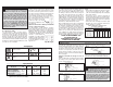
Grounded Tools: Tools with Three Prong Plugs
Tools marked “Grounding Required” have a three
wire cord and three prong grounding plug. The
plug must be connected to a properly grounded
outlet (See Figure A). If the tool should electrically
malfunction or break down, grounding provides a
low resistance path to carry electricity away from
the user, reducing the risk of electric shock.
The grounding prong in the plug is connected
through the green wire inside the cord to the
grounding system in the tool. The green wire in the
cord must be the only wire connected to the tool's
grounding system and must never be attached to
an electrically “live” terminal.
Your tool must be plugged into an ap-
propriate outlet, properly installed and
grounded in accordance with all codes
and ordinances. The plug and
outlet should look like those in
Figure A.
Double Insulated Tools:
Tools with Two Prong Plugs
Tools marked “Double Insulated” do not require
grounding. They have a special double insula-
tion system which satisfi es OSHA requirements
and complies with the applicable standards of
Underwriters Laboratories, Inc.,
the Canadian Standard Asso-
ciation and the National Elec-
trical Code. Double Insulated
tools may be used in either of
the 120 volt outlets shown in
Figures B and C.
Fig. B
Fig. C
Fig. A
GROUNDING
WARNING Improperly connecting the
grounding wire can result in the risk of
electric shock. Check with a qualifi ed electri-
cian if you are in doubt as to whether the
outlet is properly grounded. Do not modify
the plug provided with the tool. Never remove
the grounding prong from the plug. Do not
use the tool if the cord or plug is damaged. If
damaged, have it repaired by a MILWAUKEE
service facility before use. If the plug will not
fi t the outlet, have a proper outlet installed by
a qualifi ed electrician.
No Load
RPM
24,000
10,000 - 24,000
24,000
10,000 - 22,000
Volts
120 AC
120 AC
120 AC
120 AC
Specifi cations
Amps
11
13
11
15
Cat. No.
5615-20 * Bodygrip
®
5616-20 * Bodygrip
®
5619-20 D-Handle
5625-20 Production
Max
HP
1-3/4
2-1/4
1-3/4
3-1/2
* Also compatible with plunge base 48-10-5600, available
separately and in kits.
D-Handle
models