
Operating instructions


FIG
.
NO
.
Frontis-
piece
1-1
1-2
1-3
1-4
1-6
1-7
2-1
3-1
3-2
3-3
3-4
3-5
3-6
4-2
4-3
REV
JUN
1981
71387
Features
. . . . . . . . . . . . . . . . . . . . . . . . . . . . . . . .
.Location
of
release
latch
. . . . . . . . . . . . . . . . . . . . . . .
.
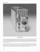
Front-panel
controls,
connectors,
and
indicators
.
.
. .
.
. .
.
. .
. .
.
. .
.
. .
.
. .
.
. .
.
. .
.
. .
.
.
.
.
. .
.
Single
Sweep
Acquisition
.
. . .
.
. .
.
. . . . . . .
.
. .
.
. . .
.
Effect
of
LEVEL
control
and
SLOPE
switch
on
crt
display
. . . .
.
. . . . . . . . . . . . . .
.
. . . . . . . . . . . . .
.Area
of
graticule
used
for
most
accurate
time
measurements
.
.
. .
. .
. .
.
. .
.
. . . . . . .
.
. .
.
. . .
.
Operation
of
sweep
magnifier
.
.
. . .
. . .
.
. . . . . . .
.
.
Measuring
the
period
and
determining
the
frequency
of
a
displayed
waveform
. . . . . . . . . . . . .
Measuring
the
rise
time
and
fall
time
of
a
displayed
waveform
. . . . . . . . . . . . . . . . . . . . . . . . .
1-14
Measuring
the
pulse
width
of
a
displayed
waveform
. . . . . . . . . . . . . . . . . . . . . . . . .
. . . . . . . . . . .
1-14
71387
dimensional
drawing
. . . . . . . . . . . . . . . . .
. .
2-5
Basic block
diagram
of
the
71387
Delaying
Time
Base
Unit
. . . . . . . . . . . . . . . . . . . . . . . . . . . . . . . .
3-2
Detailed
block
diagram
of
Trigger
Generator
. . . . .
3-4
Timing
diagram
for
Gate
Generator
stage
(092,
Q96,
098)
. . . . . . . . . . . . . . . . . . . . . . . . . . .
. . . .
3-6
Detailed
block
diagram
of
Logic
circuit
. . . . . . . . . . .
3-7
Detailed
block
diagram
of
Sweep
Generator
. .
. . . .
3-8
Timing
of
events
that
form
the
Delay
Gate
signal
. . . . . . . . . . . . . . . .
. . . . . . . . . . . . . . . . . . .
3-11
Lubrication
procedure
for
a
typical
cam
switch
. . . . . . . . . . . . . . . . .
.
. . . . . .
. .
.
. .
.
. .
.
. . .
4-2
Semiconductor
lead
configuration
. .
.
. .
. .
.
. .
.
.
. .
.
4-3
Inter-board
multi-pin
connector
assembly
.
. .
.
. .
.
.
4-4
8-1
Semiconductor
Lead
Configurations
.
8-2
Locations
of
circuit
boards
in
the
71387
.
8-3
A2-Trigger
circuit
board
assembly
.
8-4
A1-Interface
circuit
board
assembly
.
8-5
A1-Interface
circuit
board
assembly
.
8-6
A1-Interface
circuit
board
assembly
.
8-7
A4-Clock
circuit
board
assembly
.
8-8
A4-Clock
circuit
board
assembly
.
8-9
A3-Readout
circuit
board
assembly
.
8-10
A1-Interface
circuit
board
assembly
.
8-11
Test
Point
and
Adjustment
Locations
.
713£37
Instruction
The
illustrations
in
Section 8
are
located
near
their
associated
diagrams
on
the foldout
pages
.
AGE
FIG
.
NO
.
PAGE
4-4 End-lead
multi-pin
connector
assembly
.
. .
.
. .
.
. .
.
4-4
.
viii
4-5
Location
of
pin
numbers
on
Interface
1
-1
connector
. . .
.
. .
.
. .
.
. .
.
. .
.
.
.
.
. .
.
.
.
.
. .
.
. .
.
. .
.
. .
.
4-5
4-6
71387 troubleshooting
chart
. .
.
. .
.
. .
.
.
.
.
. .
.
. .
.
. . .
4-7
1-2
4-7
Readout
board
removal
procedure
.
.
.
. .
.
. .
.
. . . . .
4-10
1-5
4-8
Coaxial
end-lead
connector
assembly
.
.
.
. . . . . . . .
4-11
4-9
Location
of
securing
screws
and
inter-board
1-10
multi-pin
connectors on
clock
circuit
board
. . . . . .
4-12
4-10
Cam
switch
removal procedure
. . . . . . . . . . . . . . . .
4-13
1-11
4-11
Removal
procedure
for
typical
pushbutton
1-12
switch
. . . . . .
.
. .
.
.
. . . . . . . . . . . . . . . . . . . . . . . . . . . .
4-14
4-12
Exploded view
of
circuit-board
pin
and
1-13
ferrule
. . . . . . . . . . . . . . . . . . . . . . . . . . . . . . . . . . . . . . .
4-16
4-13
Front-panel
light
socket
assembly
. . . . . . . . . . . . . .
4-16