OPERATOR'S MANUAL MANUEL de L'UTILISATEUR MANUAL del OPERADOR Cat. No. No de cat. 6276-20 JIG SAW SCIE SAUTEUSE SIERRA CALADORA TO REDUCE THE RISK OF INJURY, USER MUST READ AND UNDERSTAND OPERATOR'S MANUAL. AFIN DE RÉDUIRE LE RISQUE DE BLESSURES, L'UTILISATEUR DOIT LIRE ET BIEN COMPRENDRE LE MANUEL DE L'UTILISATEUR. PARA REDUCIR EL RIESGO DE LESIONES, EL USUARIO DEBE LEER Y ENTENDER EL MANUAL DEL OPERADOR.
GENERAL POWER TOOL SAFETY WARNINGS WARNING READ ALL SAFETY WARNINGS AND ALL INSTRUCTIONS. 2 Failure to follow the warnings and instructions may result in electric shock, fire and/or serious injury. Save all warnings and instructions for future reference. The term "power tool" in the warnings refers to your mains-operated (corded) power tool or battery-operated (cordless) power tool. attached to a rotating part of the power tool may WORK AREA SAFETY result in personal injury.
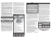
SERVICE SPECIFICATIONS •Have your power tool serviced by a qualified repair person using only identical replacement parts. This will ensure that the safety of the power tool is maintained. Cat. No. 6276-21 GROUNDING No Load Volts Amps Strokes of Per Length AC Stroke Minute 120 6.2 500-3000 1" SPECIFIC SAFETY RULES •Hold power tool by insulated gripping surfaces, when performing an operation where the cutting accessory may contact hidden wiring or its own cord.
ASSEMBLY Adjusting the shoe The shoe may be tilted up to 45° in either direction and moved forward or backward. To set a tilt angle for angle cuts and bevels, loosen the shoe adjustment lever and pull the base forward slightly until the retaining lugs are no longer engaged. Tilt the shoe to the required preset angle (15°, 30°, or 45°) as read on the tilt angle scale. Push back the shoe into the retaining lugs and tighten the shoe adjustment lever.
LIMITED WARRANTY - USA AND CANADA MAINTENANCE WARNING To reduce the risk of explosion, electric shock and property damage, always check the work area for hidden gas pipes, electrical wires or water pipes when making blind or plunge cuts. WARNING To reduce the risk of injury, always unplug your tool before performing any maintenance. Never disassemble the tool or try to do any rewiring on the tool’s electrical system. Contact a MILWAUKEE service facility for ALL repairs.
RÈGLES DE SÉCURITÉ GÉNÉRALES RELATIVES AUX OUTILS ÉLECTRIQUES AVERTISSEMENT LIRE TOUTES LES RÈGLES ET INSTRUCTIONS DE SÉCURITÉ. Ne pas suivre l’ensemble des règles et instructions peut entraîner une électrocution, un incendie ou des blessures graves. Conserver les règles et les instructions à des fins de référence ultérieure. Le terme «outil électrique» figurant dans les avertissements cidessous renvoie à l’outil électrique à alimentation par le réseau (à cordon) ou par batterie (sans fil).
MISE A LA TERRE MONTAGE DE L’OUTIL CORDONS DE RALLONGE Si l’emploi d’un cordon de rallonge est nécessaire, un cordon à trois fils doit être employé pour les outils mis à la terre. Pour les outils à double isolation, on peut employer indifféremment un cordon de rallonge à deux ou trois fils. Plus la longueur du cordron entre l’outil et la prise de courant est grande, plus le calibre du cordon doit être élevé.
MANIEMENT Réglage de fréquence des cycles/min. La fréquence des cycles Matériau Vitesse de par minute peut être réglée coupe reà l’aide de l’indicateur de commandée vitesse. Les chiffres de Bois 7 1 à 7 sont imprimés sur 4-5 l’indicateur. Le chiffre 1 Métal correspond à la vitesse Plastique 2 minimale tandis que le chiffre 7 indique la vitesse maximale. Les vitesses de coupe recommandées pour divers matériaux sont indiquées ci-dessous.
GARANTIE LIMITÉE - AUX ÉTATS-UNIS ET AU CANADA Chaque outil électrique MILWAUKEE (y compris les produits sans fil [outils, piles, chargeur de piles, lampe de travail]; consulter les énoncés de la GARANTIE LIMITÉE DES BLOCS-PILES SANS FIL) est garanti à l’acheteur d’origine être exempt de vice de matériau et de fabrication.
•ADVERTENCIA : Algunas partículas de polvo resultantes del lijado mecánico, aserrado, esmerilado, taladrado y otras actividades relacionadas a la construcción, contienen sustancias químicas que se saben ocasionan cáncer, defectos congénitos u otros daños al aparato reproductivo.
Cómo ajustar la zapata La zapata se puede inclinar hasta 45° en ambas direcciones y moverse hacia delante o hacia atrás. Para establecer el ángulo de inclinación para cortes en ángulo y en bisel, afloje la palanca de ajuste de la zapata y tire de la base levemente hacia delante hasta que las orejetas de retención se desenganchen. Incline la zapata al ángulo preestablecido requerido (15°, 30° o 45°) según se lee en la escala de ángulo de inclinación.
ADVERTENCIA Para reducir el riesgo de explosión, descarga eléctrica y daños a la propiedad, verifique que en el área de trabajo donde realizará cortes ciegos o penetrantes no hayan tuberías de gas, cables ni tuberías de agua ocultas. Cómo realizar cortes de hundimiento Los cortes de hundimiento pueden realizarse en Fig. 5 materiales suaves sin la necesidad de un orificio pretaladrado. Los materiales más duros requieren un orificio piloto con un diámetro un poco mayor que el ancho de la cuchilla.
UNITED STATES MILWAUKEE Service MILWAUKEE prides itself in producing a premium quality product that is NOTHING BUT HEAVY DUTY®. Your satisfaction with our products is very important to us! If you encounter any problems with the operation of this tool, or you would like to locate the factory Service/Sales Support Branch or authorized service station nearest you, please call... Additionally, we have a nationwide network of authorized Distributors ready to assist you with your tool and accessory needs.