
Operator`s manual


16
17
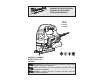
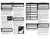
FUNCTIONAL DESCRIPTION
1.Quik-Lok
tension lever
2.Transparent
blade cover
3. Anti-Splinter
Device
4. Blade
5. Shoe cover
6. Shoe
7. Orbital action
selector lever
7
6
5
9
11
10
8
12
13
8. Shoe adjustment
lever
9. Tilt angle scale
10. Dust collection
attachment
11. Trigger
12. Lock button
13. Speed selector dial
4
2
1
3
SYMBOLOGY
Double Insulated
Volts
Alternating Current
W
Watts
No Load Revolutions per
Minute (RPM)
Seal of Electrical Security
Read operator's manual
Wear hearing protection
Wear eye protection
Fig. B
Fig. C
Fig. A
GROUNDING
Grounded Tools: Tools with Three Prong Plugs
Tools marked “Grounding Required” have a three
wire cord and three prong grounding plug. The
plug must be connected to a properly grounded
outlet (See Figure A). If the tool should electrically
malfunction or break down, grounding provides a
low resistance path to carry electricity away from
the user, reducing the risk of electric shock.
The grounding prong in the plug is connected
through the green wire inside the cord to the
grounding system in the tool. The green wire in the
cord must be the only wire connected to the tool's
grounding system and must never be attached to
an electrically “live” terminal. Your tool must
be plugged into an appropriate outlet, prop-
erly installed and grounded in accordance
with all codes and ordinances. The
plug and outlet should look like
those in Figure A.
Double Insulated Tools: Tools
with Two Prong Plugs
Tools marked “Double Insulated” do not require
grounding. They have a special double insulation
system which satisfi es OSHA requirements and com-
plies with the applicable standards of
Underwriters Laboratories, Inc., the
Canadian Standard Association and
the National Electrical Code. Double
Insulated tools may be used in ei-
ther of the 120 volt outlets shown in
Figures B and C.
In specifi c countries, double insulated tools could
be used in the output connections suitable for
the plug.
WARNING Improperly connecting the
grounding wire can result in the risk of elec-
tric shock. Check with a qualifi ed electrician
if you are in doubt as to whether the outlet is
properly grounded. Do not modify the plug
provided with the tool. Never remove the
grounding prong from the plug. Do not use
the tool if the cord or plug is damaged. If
damaged, have it repaired by a MILWAUKEE
service facility before use. If the plug will not
fi t the outlet, have a proper outlet installed by
a qualifi ed electrician.
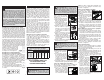
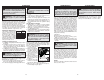
Anti-splinter
device
Shoe
1. Unplug tool.
2. Slide the anti-splinter de-
vice onto the shoe. Make
sure the anti-splinter device
is installed fl ush with the
bottom of the shoe.
NOTE: Do not use the anti-
splinter device or dust collec-
tion attachment when making
bevel/angle cuts.
Using the shoe cover
The shoe cover is used to
prevent marring and scratch-
ing of the workpiece surface.
To attach the shoe cover:
1. Unplug tool.
2. Hook the front of the cover
over the steel shoe.
3. Snap the rear of the shoe
cover over the back of the
shoe. Be sure both sides are snapped in place.
4. When the shoe cover is not needed, remove it by
pulling the tabs on rear of the shoe cover down.
Unhook the front of the shoe cover and remove.
Using the Dust Collection Attachment
1. Unplug tool.
2. To install, line-up the small end of the dust col-
lection attachment with the curved area at the
back of the shoe. Slide into place. The clip on
the top of the attachment will slide into the slot
on the underside of the jigsaw motor housing.
3. To remove, press up on the clip and slide at-
tachment away from jigsaw.
NOTE: Do not use the anti-splinter device or dust
collection attachment when making bevel/angle
cuts.
Adjusting the Shoe
The shoe may be tilted
up to 45° in either direc-
tion. To set a tilt angle for
bevel/angle cuts:
1. Unplug tool.
2. Remove anti-splinter
device and dust collec-
tion attachment.
3. Loosen the shoe ad-
justment lever and
pull the base forward
slightly until the detents
are not engaged.
4. Tilt the shoe to the required preset angle
(0°, 15°, 30°, or 45°).
5. Push the shoe into the detent and tighten the
shoe adjustment lever.
6. To set an angle other than 0°, 15°, 30°, or 45°,
loosen the shoe adjustment lever and pull the
base forward slightly until the detents are not
engaged. Set the desired angle and tighten the
shoe adjustment lever without engaging a detent.
Make a test cut to verify the angle.
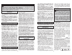
Using the Transparent Blade Cover
1. Unplug tool.
2. To install, place
the transparent
blade cover in front
of the blade and
slide it into place. The
tabs will snap into the
slots on the housing.
3. To remove, press
in the sides of the
transparent blade cover and pull away from the
blade.
Using the Anti-Splinter Device
The anti-splinter device helps stabilize the work-
piece and reduce workpiece splinter.
WARNING To reduce the risk of injury,
always use saw with transparent blade cover
in place. Sawdust and wood chips can be
thrown during use.
Slot
Blade
ASSEMBLY
Installing Saw Blades
Use only T-Shank jig saw
blades.
1. Unplug tool.
2. Remove anti-splinter
device and transparent
blade cover.
3. Pull out and hold the
Quik-Lok tension lever.
4. Fit the saw blade into
the groove in the support
roller and push it fi rmly into the plunger as far
as it will go; the lug of the saw blade must be in
the plunger.
5. Release the Quik-Lok tension lever to secure
the saw blade.
6. Check that the saw blade is held fi rmly; the slot
in the plunger will be at an angle to the blade.
7. Install the anti-splinter device and transparent
blade cover.
WARNING To reduce the risk of injury,
always unplug tool before attaching or remov-
ing accessories or making adjustments. Use
only specifi cally recommended accessories.
Others may be hazardous.
WARNING To reduce the risk of injury,
wear safety goggles or glasses with side shields.