
Product Manual


page 6
TOOL ASSEMBLY
To reduce the risk of injury, always unplug
tool before attaching or removing accessories
or making adjustments. Use only specifically
recommended accessories. Others may be
hazardous.
WARNING!
Fig. 1
Fig. 4
Fig. 6
1/4"
Fig. 5
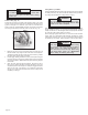
4. Move the depth adjusting lever towards the shoe and push down to
secure the position.
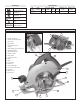
Adjusting Bevel Angle (Fig. 6 & 7)
1. Unplug tool.
2. To adjust the angle of the cut, hold the saw by the Tilt-Lok™ handle
and loosen the bevel adjusting lever by lifting it up towards the
blade (Fig. 6).
3. Raise or lower the shoe to the desired position. Markings in 1/4"
increments are located on the inner side of the upper guard for depth
setting. For the proper depth setting, the blade should extend no
more than 1/4" below the material being cut (Fig. 5).
Adjusting Depth (Fig. 4 & 5)
1. Unplug tool.
2. To adjust the depth of the cut, hold the saw by the Tilt-Lok™ handle
and loosen the depth adjusting lever by lifting it up and away from the
shoe (Fig. 4).
Selecting Blade
Always use sharp blades. Dull blades tend to overload the tool and increase
the chance of KICKBACK (see page 8). Only use blades with a maximum
safe operating speed greater than the no load RPM marked on the tool’s
nameplate. Read the blade manufacturer’s instructions before use.
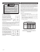
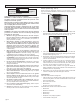
Installing and Removing Blades (Fig. 1, 2 & 3)
1. Unplug tool before installing or removing blades.
2. Place the saw on a flat surface with the blade facing upwards. To
remove the bolt from the spindle, push in the spindle lock button.
While holding the spindle lock button in, use the wrench provided
with the tool to turn the bolt clockwise (Fig. 1). Remove the bolt and
outer blade flange. Do not remove inner blade flange.
6. While holding the spindle lock button in, use the wrench to turn the
bolt counterclockwise and tighten.
3. Slide the lower guard lever up to raise the lower guard. Remove the
blade from the spindle. Always clean the spindle, upper guard and
lower guard to remove any dirt and sawdust.
4. To install a blade, place the blade on the spindle with the teeth
pointing in the same direction as the arrow on the lower guard
(Fig. 2). Larger diameter of inner flange (Fig. 3) should rest on blade.
Release the lower guard lever.
5. Place the outer blade flange on the spindle and hand tighten the bolt.
Larger diameter of outer flange (Fig. 3) should rest on blade.
Fig. 3
Inner
flange
Outer
flange
Fig. 2