
Product Manual
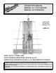
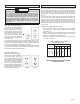


page 6
WARNING!
TOOL ASSEMBLY
To reduce the risk of injury, always unplug tool before
attaching or removing accessories or making adjustments.
Use only specifically recommended accessories. Others may
be hazardous.
Assembly Order
To avoid injury or damage to the tool, follow the order of sections in "Tool
Assembly". Set up the tool in the following order of sections:
1. Setting up the Stand
2. Installing the Counterbalance
3. Mounting the Saw Motor
4. Installing Blades
5. Adjusting the Rulers
6. Installing the Blade Guard
7. Installing the Cord Keeper
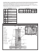
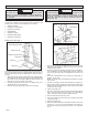
Setting up the Stand (Fig. 1)
Use at least two people to remove packaging and set up the stand. One
person should hold the stand in an upright position while the other re-
moves the packaging and sets the folding stand to make the tool free-
standing.
1. While having another person hold the stand in the upright position,
stand behind the tool. Remove the locking pin from the folded locking
pin position with one hand while holding the stand base with your
other hand so it does not unfold onto your feet.
2. Unfold the stand slowly until the hole in the sliding center bar is
aligned with the hole in the center bar.
3. Insert the locking pin through the holes and lock it securely.
Sliding center bar
Folded locking pin position
Locking pin
Center bar
Unfolded locking pin position
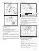
Installing the Counterbalance (Fig. 2 & 3)
WARNING!
To reduce the risk of injury or damage to components, do not
attempt to disassemble or repair the counterbalance. Do not
pull on the counterbalance cable. The cable is under strong
spring force. Unit must be properly assembled before re-
moving cable clip.
1. Remove the (2) 1/4" nuts, (2) washers and (2) 1/4" x 1/2" carriage
bolts from the counterbalance. Leave the nut and bolt on the coun-
terbalance cable in place.
2. Remove the end of the cable from the inside of the counterbalance.
The counterbalance can be installed slightly off-center to either the
left or to the right: four holes are predrilled into the top of the tool
frame.
3. Secure the counterbalance to the tool using (2) carriage bolts, (2)
washers, and (2) nuts.
NOTE: The carriage bolts are installed from the bottom up. Tighten
nuts securely.
4. Hold the saw carriage securely while loosening the carriage lock.
5. Raise the saw carriage until the oval hole in the saw carriage aligns
with the eye hole in the counterbalance cable, making sure the cable
is behind the saw carriage.
6. Tighten the carriage lock.
7. Remove the nut from the carriage bolt and insert the bolt through the
hole in the saw carriage and the eye hole in the counterbalance
cable. Thread the nut onto the bolt and tighten securely.
8. Bend the cable clip tabs forward by hand.
9. Loosen the carriage lock and lower the saw carriage until the cable
clip is fully exposed.
10. Tighten the carriage lock.
11. Remove the cable clip from the counterbalance cable and save it for
future use (i.e., If you remove the counterbalance in the future, you
will need the cable clip to support the tension in the counterbal-
ance.)
Fig. 1
Fig. 2
Fig. 3
Counterbalance
Counterbalance
cable
Nut
Washer
Carriage bolt
Cable clip
Counterbalance
cable
Carriage
bolt
Cable clip tabs
Nut
Stand base